Apparatus and method for irradiating a medium
a technology of irradiation and apparatus, applied in the field of apparatus and a method for irradiation of a medium, can solve the problems of loss of directionality of light as well as information associated, difficult to extract detailed internal information about a medium, and difficult to obtain internal information through detection of scattered ligh
- Summary
- Abstract
- Description
- Claims
- Application Information
AI Technical Summary
Problems solved by technology
Method used
Image
Examples
first embodiment
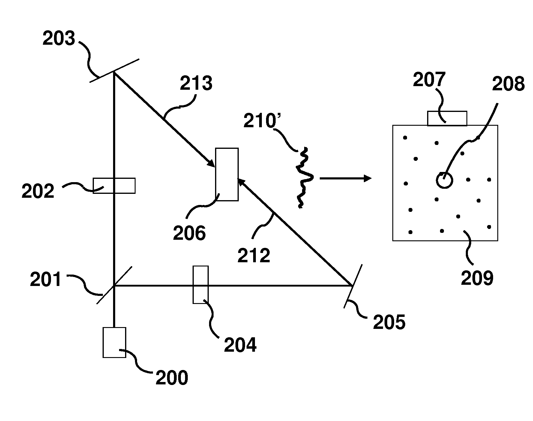
[0062]An irradiating apparatus and method according to a first embodiment of the present invention will be described below. FIGS. 3A and 3B are schematic diagrams illustrating an exemplary configuration of a recording step (FIG. 3A) and a reproducing step (FIG. 3B), respectively.
[0063]The first embodiment includes an acousto-optic imaging technique. A laser 300 emits an initial light and the initial light is split into an incident light beam 314 and a reference light beam 315 by a beam splitter 301 in FIG. 3A. The incident light beam 314 and the reference light beam 315 enter AOM 302 and AOM 305, respectively. The frequencies of those two AOMs are typically 50 MHz to 80 MHz, and are slightly different by an amount equal to the frequency applied to an ultrasound system 311, which ranges from approximately 1 to tens of megahertz. The role of these AOMs may be the same as described above.
[0064]A lens system 303 controls the beam size of the incident light 314, and a movable mirror 304 ...
second embodiment
[0081]An irradiating apparatus and method according to a second embodiment of the present invention will now be described. The configuration of an imaging system in this embodiment is same as that of in the first embodiment shown in FIG. 3A and FIG. 3B, except for adding photodetectors around the scattering medium 312 (not shown). The imaging system in the second embodiment includes a technique called diffuse optical tomography (DOT).
[0082]The flow may also be the same as in the first embodiment until the hologram has been developed in the photorefractive crystal 307. Once the hologram has been created in the photorefractive crystal 307, the backward pump light beam 317 illuminates the photorefractive crystal 307 to generate the phase conjugation beam (including the phase conjugate wave) 318. At this moment, the ultrasound system 311 may be turned off to perform DOT measurement.
[0083]After this phase conjugation beam 318 enters the scattering medium 312, it can retrace to the ultras...
third embodiment
[0090]An irradiating apparatus and method according to a third embodiment of the present invention will be described. FIG. 4 is a schematic diagram illustrating an exemplary configuration of an imaging system with the irradiating apparatus according to the embodiment. The system of this embodiment may include two combined systems, which are an acousto-optic imaging system and a photoacoustic imaging system.
[0091]A laser source 400 (a first electromagnetic wave source as a part of a first irradiating unit) emits initial light and is split into an incident light beam 415 and a reference light beam 416 by a beam splitter 401. An AOM 402 and AOM 405 have a same role as already described above to adjust the frequency. the incident light beam 415 enters a scattering medium 409 through an optical system 406.
[0092]An ultrasound system 407 including an ultrasound device, which may be acoustically matched to the medium 409, controls an ultrasound focus volume 408 with size and position inside...
PUM
 Abstract
Description
Claims
Application Information
 - R&D
- Intellectual Property
- Life Sciences
- Materials
- Tech Scout
- Unparalleled Data Quality
- Higher Quality Content
- 60% Fewer Hallucinations
Browse by: Latest US Patents, China's latest patents, Technical Efficacy Thesaurus, Application Domain, Technology Topic, Popular Technical Reports.
© 2025 PatSnap. All rights reserved.Legal|Privacy policy|Modern Slavery Act Transparency Statement|Sitemap|About US| Contact US: help@patsnap.com


