
Pre-Coding Method and Apparatus Based on Mixed Multiplexing Demodulation Reference Signals

Active Publication Date: 2012-11-29
G+ COMMUNICATIONS LLC
View PDF19 Cites 19 Cited by
  • Summary
  • Abstract
  • Description
  • Claims
  • Application Information

AI Technical Summary

Benefits of technology

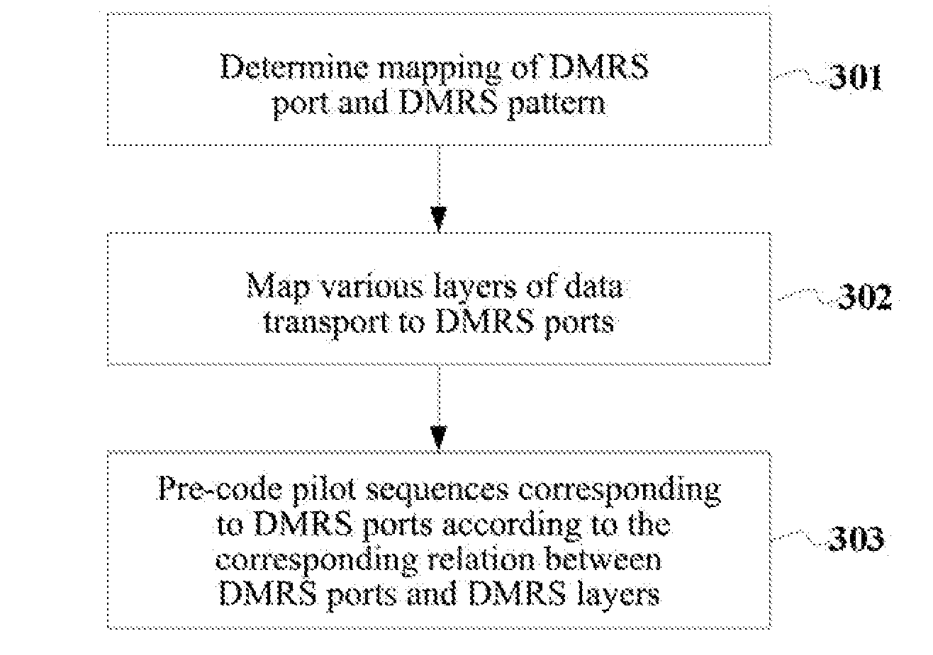
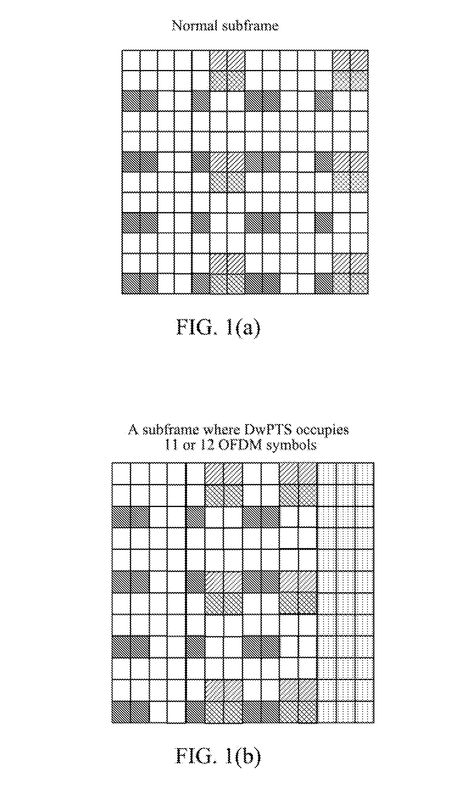
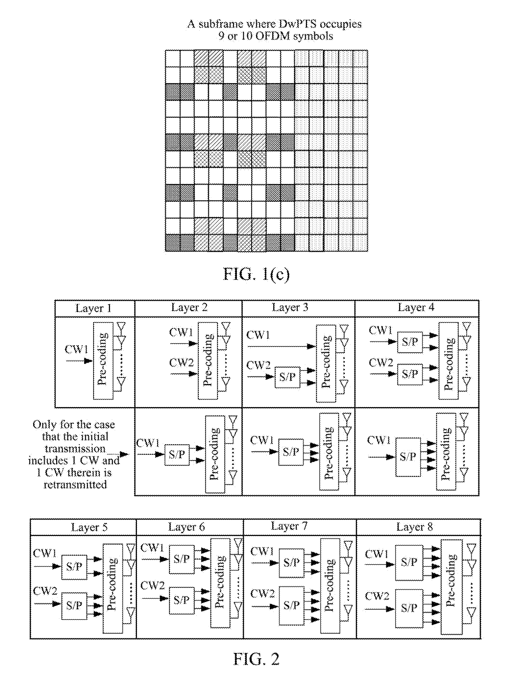
[0010]Based on the DMRS pattern of the subframe defined in the related art, how to map the demodulation reference symbol of the layer corresponding to each codeword stream and map the same to which RE groups are problems to be designed and taken into account. Good allocation manner is advantageous for improving system performance and at the same time reducing signaling overhead, therefore, it is necessary to propose a mapping manner so as to reduce the probability of random mapping and reduce signaling overhead.
[0011]The technical problem to be solved by the present invention is to provide pre-coding method and apparatus based on a hybrid multiplexing demodulation reference symbol, so as to avoid interference between the layers corresponding to different codeword streams.
[0069]By way of the technical solution of the present invention, interference between the layers corresponding to different codeword streams can be avoided, and the accuracy of channel estimation can be improved. At the same time, since the technical solution of the present invention employs a fixed mapping manner, the probability of random mapping is reduced and the overhead of the control signaling is also reduced.

Problems solved by technology

Such common reference signal requires the transmission side to notify the receiving end which preprocessing manner is used on the transmitted data, and also the overhead is considerable; furthermore, in a multi-user multi-input multi-output (MU-MIMO) system, since a plurality of user equipment (UE) use the same CRS, the orthogonality of pilots cannot be realized, and the interference cannot be estimated.

Method used


Image

  • Pre-Coding Method and Apparatus Based on Mixed Multiplexing Demodulation Reference Signals
  • Pre-Coding Method and Apparatus Based on Mixed Multiplexing Demodulation Reference Signals
  • Pre-Coding Method and Apparatus Based on Mixed Multiplexing Demodulation Reference Signals

Examples


embodiment 1

[0130]This embodiment takes a SU-MIMO system as an example to describe the mapping manner from the layer of codeword stream to DMRS port. In the SU-MIMO, when the total number of layers corresponding to each codeword stream is less than or equal to the number of orthogonal code division multiplexing layers supported by the RE corresponding to each group of CDM multiplexing DMRS ports (i.e. the maximum number of ports supported in the DMRS port group), the mapping manner is as follows:

[0131]the DMRS ports of each layer corresponding to the same codeword stream employ the same multiplexing manner (i.e. the layers corresponding to the same codeword stream are mapped to the DMRS ports of the same DMRS group), such as code division multiplexing manner; the same or different multiplexing manner is used between the DMRS ports of the layers corresponding to different codeword streams (i.e. the layers corresponding to different codeword streams are mapped to the DMRS ports of different DMRS ...

embodiment 2

[0142]This embodiment takes a MU-MIMO system as an example to describe the mapping process from the layers corresponding to a codeword stream to DMRS ports. In the MU-MIMO, the rule of allocating a DMRS port to each user is that: as to each user, various layers corresponding to the same user are mapped to the DMRS ports with the same multiplexing manner.

[0143]In this case, the same multiplexing manner refers to: the layers corresponding to the same user are mapped to the DMRS ports of the port group employing CDM with priority, or the layers corresponding to the same user are mapped to DMRS ports of the port group employing FDM / TDM with priority (i.e. the DMRS ports of different DMRS port groups). The configuration of defining MU-MIMO includes the following parameters:

[0144]the maximum number of layers supported by the MU-MIMO system, the maximum number of multiplexing users supported and the maximum number of layers transmitted by each multiplexing user;

[0145]the values of the abov...

embodiment 3

[0150]In this embodiment, SU-MIMO and MU-MIMO employ a unified mapping manner from layer to DMRS port, and considering that SU-MIMO and MU-MIMO employ a fixed mapping from layer to DMRS port, a fixed relationship can be set between the layer and DMRS port, and DMRS ports {p0, p1, p2, p3, p4, p5, p6, p7} are defined. It is in particular as follows:

[0151]when the number of layers is less than or equal to 2, the relationship between layer and DMRS port can be set as:

[0152]layer0port0[0153]layer1port1

[0154]when the number of layers is greater than 2 and less than or equal to 4, the relationship between layer and DMRS port can be set as:

[0155]layer0port0[0156]layer1port1[0157]layer2port2[0158]layer3port3

[0159]when the number of layers is greater than 4 and less than or equal to 8, the relationship between layer and DMRS port can be set as:[0160]layer0port0[0161]layer1port1[0162]layer2port2[0163]layer3port3[0164]layer4port4[0165]layer5port6[0166]layer6port5[0167]layer7port7

[0168]In this c...


PUM


Abstract

Disclosed in the present invention is a pre-coding method for hybrid multiplexing demodulation reference symbol (DMRS). The method includes: determining a multiplexing relationship between DMRS ports; making layers of data transport correspond to DMRS ports with the multiplexing relationship determined; and pre-coding pilot sequences corresponding to various DMRS ports according to the relationship between the layers of data transport and the DMRS ports. Also disclosed in the present invention is a method for mapping from a layer to a multiplexing demodulation reference symbol (DMRS) and an apparatus for achieving pre-coding based on a hybrid multiplexing demodulation reference symbol (DMRS). By way of the technical solution of the present invention, interference between the layers corresponding to different codeword streams can be avoided, and the accuracy of channel estimation can be improved.

Description

TECHNICAL FIELD[0001]The present invention relates to the long term evolution advanced (LTE-A) technology, and in particular, to a pre-coding method and apparatus based on a hybrid multiplexing demodulation reference symbol.BACKGROUND OF THE RELATED ART[0002]The high order multi-antenna technology is one of the critical technologies of the long term evolution advanced (LTE-A or LTE-Advanced) system for improving the transmission rate of the system. In order to achieve channel quality measurement and data demodulation after the high order multi-antenna technology is introduced, the LTE-Advanced system respectively defines two types of pilot symbols: demodulation reference symbol (DMRS) and channel quality measurement-reference symbol (CSI-RS), wherein the demodulation reference symbol is a reference symbol used for the demodulation of a physical downlink shared channel (PDSCH). The measurement reference symbol is a reference symbol used for measuring channel state information (CSI) a...

Claims


Application Information

Patent Timeline
IPC IPC(8): H04L29/02
CPCH04L5/0023H04L5/0051H04L2025/03426H04L25/0226H04L2025/03414H04L25/0204H04L1/06H04L27/26
Inventor SUN, YUNFENGZHANG, WENFENGJIANG, JINGZHANG, JUNFENG
Owner G+ COMMUNICATIONS LLC
Learn More