Method of and apparatus for mapping to demodulation reference signal port

a reference signal and port mapping technology, applied in the field of digital communication, can solve the problems of inconvenient scheduling of rels, no port mapping method in the existing solution, etc., and achieve the effect of reducing the overhead of demodulation reference signals

Active Publication Date: 2012-11-29
DATANG MOBILE COMM EQUIP CO LTD
View PDF22 Cites 26 Cited by
  • Summary
  • Abstract
  • Description
  • Claims
  • Application Information

AI Technical Summary

Benefits of technology

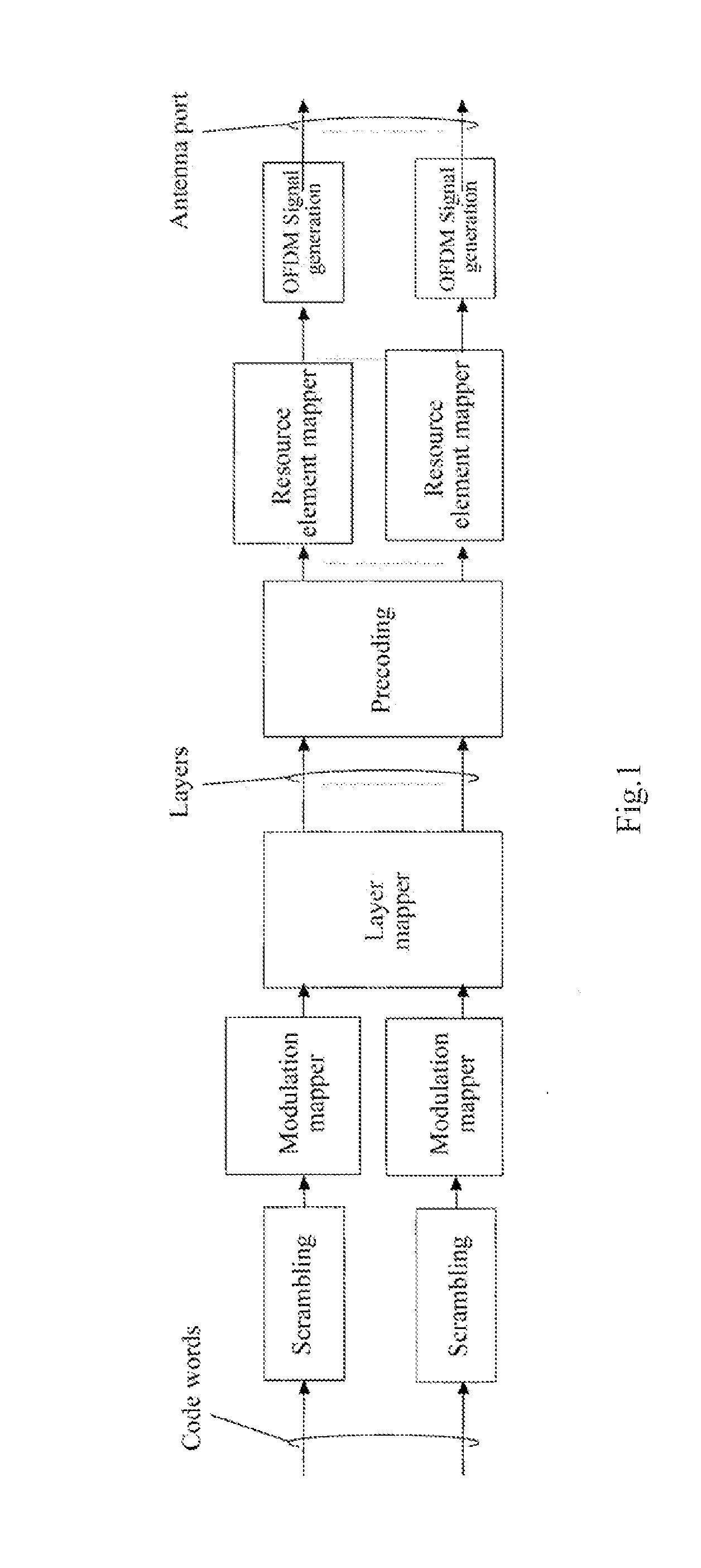
[0016]An object of the invention is to address at least one of the foregoing drawbacks in the prior art, particularly by defining a solution to mapping to a demodulation reference signal port at the rank=1 to the rank=8 and a solution to mapping to a demodulation reference signal port in retransmission, so that the solutions to mapping to a demodulation reference signal port can be compatible with an existing system while keeping a lower demodulation reference signal overhead.
[0021]The foregoing solutions proposed by the invention define a solution to mapping to a demodulation reference signal port at the rank=1 to the rank=8, and a solution to mapping to a demodulation reference signal port in retransmission, so that the solutions to mapping to a demodulation reference signal port can be compatible with an existing system while keeping a lower demodulation reference signal overhead. Furthermore the foregoing solutions proposed by the invention make minor modification to the existing system without any influence upon continual evolvement of the system and can be simple and efficient to implement.

Problems solved by technology

(1) At the rank=2, two codewords have to be mapped respectively into different CDM groups under the mapping rule thereof, and this mapping scheme is incompatible with the transmission mode 8 of the Rel-9, so it is inconvenient to schedule an Rel-9 UE and an Rel-10 UE jointly;
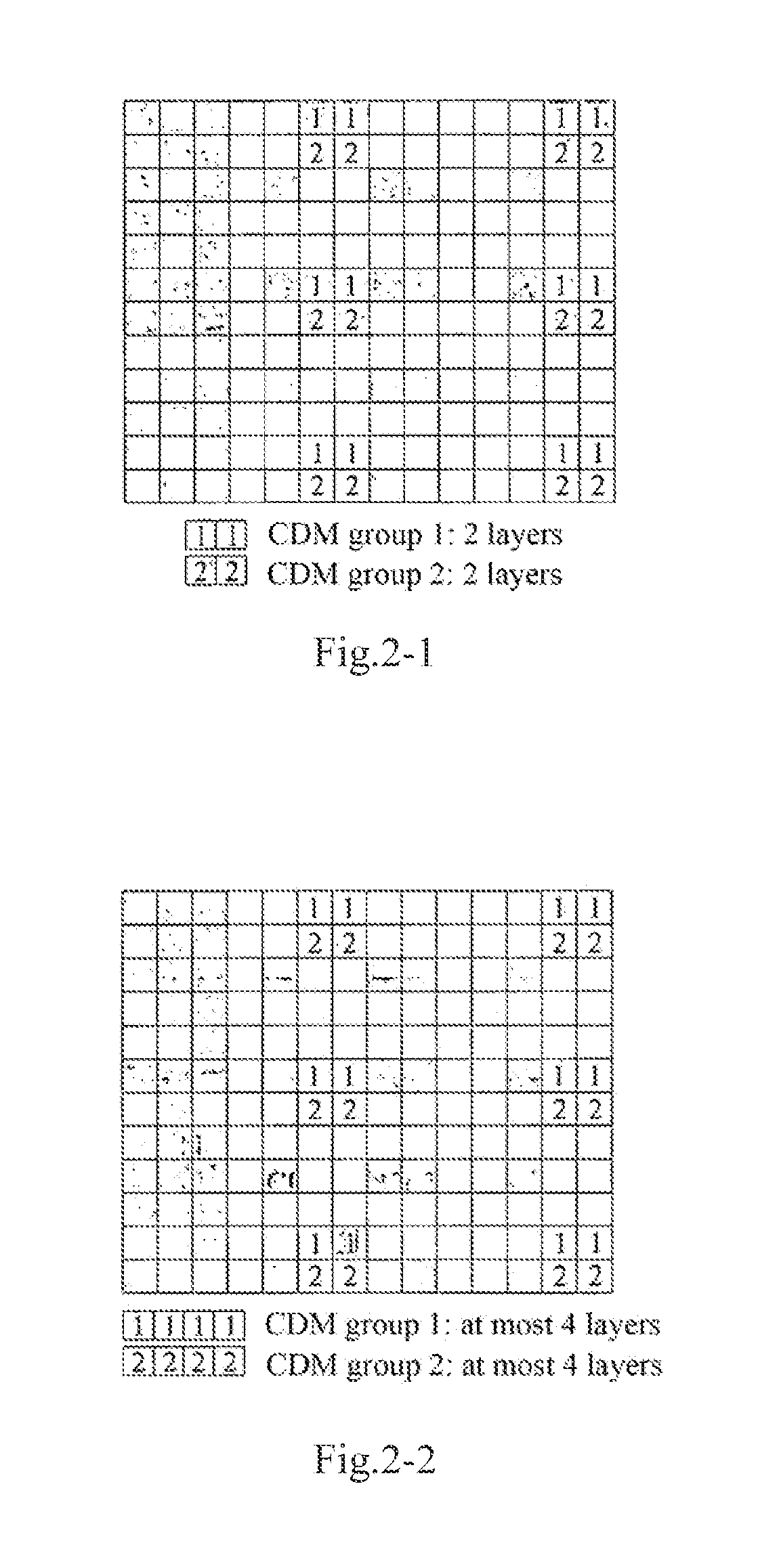
(2) At the rank=2, two codewords have to be mapped respectively into different CDM groups, and therefore a DMRS overhead is increased from 12 pairs of Resource Elements (REs) / Physical Resource Blocks (PRBs) to 24 pairs of REs / PRBs;
(3) If it is ensured under the principle of the existing solution that a layer corresponding to each codeword can only be put into one CDM group with a DRMS overhead of 12 pairs of REs / PRBs, then only transmission of a single codeword can be supported in transmission at the rank=2; and
(4) No method of port mapping in retransmission has been considered in the existing solution.

Method used


Image

  • Method of and apparatus for mapping to demodulation reference signal port
  • Method of and apparatus for mapping to demodulation reference signal port
  • Method of and apparatus for mapping to demodulation reference signal port

Examples


Embodiment Construction

[0038]Embodiments of the invention will be described below in details, and examples of the embodiments will be illustrated in the drawings throughout which identical or similar reference numerals denote identical or similar elements or elements with identical or similar functions. The embodiments to be described below with reference to the drawings are illustrative and intended to just explain the invention but can not be construed as limiting the invention.

[0039]In order to attain the object of the invention, an embodiment of the invention discloses a method of mapping to a demodulation reference signal port, which includes the following steps:

[0040]A base station assigns a UE with a corresponding data stream dependent upon an attribute of the UE; the base station maps the corresponding data stream from a layer to a corresponding demodulation reference signal port; and the base station transmits the corresponding data stream to the UE via the demodulation reference signal port.

[004...


PUM


Abstract

A demodulation reference signal port mapping method is disclosed. The method includes: a base station communicates with a User Equipment (UE), and allocates corresponding data stream to the UE according to the attribution of the UE; the base station maps the corresponding data stream from a layer to a corresponding demodulation reference signal port; the base station transmits the corresponding data stream to the UE via demodulation reference signal port. By restricting the demodulation reference signal port mapping solution of rank=1 to rank=8 and the demodulation reference signal port mapping solution when the retransmission occurs, the technical solution enables the demodulation reference signal port mapping solution to compatible with the present system and to keep lower overhead of the demodulation reference signal.

Description

[0001]The present application is a US National Stage of International Application No. PCT / CN2011 / 000191, filed 31 Jan. 2011, designating the United States, and claiming priority to Chinese Patent Application No. 201010112140.X filed 11 Feb. 2010.FIELD OF THE INVENTION[0002]The present invention relates to the field of digital communications, and more particularly, the invention relates to a method of and apparatus for mapping to a demodulation reference signal port.BACKGROUND OF THE INVENTION[0003]Mobility and a broadband have become development trends of modern communication technologies, and the 3rd Generation Partnership Project (3GPP) devotes itself to evolution of a Long Term Evolution (LTE) system as a 3G system and aims to evolve 3GPP radio access technologies toward high-data-rate, low-delay and optimized packet data applications.[0004]For a higher peak rate, Single User Multi-Input Multi-Output (SU-MIMO) of Long Term Evolution Advanced (LTE-A) can support parallel transmiss...

Claims


Application Information

Patent Timeline
Patent Type & Authority Applications(United States)
IPC IPC(8): H04W4/00
CPCH04L5/0037H04L5/0026H04L1/1893H04L5/0058H04L5/0051H04L27/28
Inventor SU, XINMIAO, DESHANTAMRAKAR, RAKESH
Owner DATANG MOBILE COMM EQUIP CO LTD
Why Eureka
Try Eureka