Fan module

a technology of fan module and fan body, which is applied in the direction of machines/engines, liquid fuel engines, instruments, etc., can solve the problem of reducing the structure strength of the thinner top cover and achieving the effect of improving the structure strength

Inactive Publication Date: 2012-11-29
COMPAL ELECTRONICS INC
View PDF13 Cites 13 Cited by
  • Summary
  • Abstract
  • Description
  • Claims
  • Application Information

AI Technical Summary

Benefits of technology

[0008]Accordingly, the invention is directed t

Problems solved by technology

However, a thinner top cover has acc

Method used


Image

  • Fan module
  • Fan module
  • Fan module

Examples


Embodiment Construction

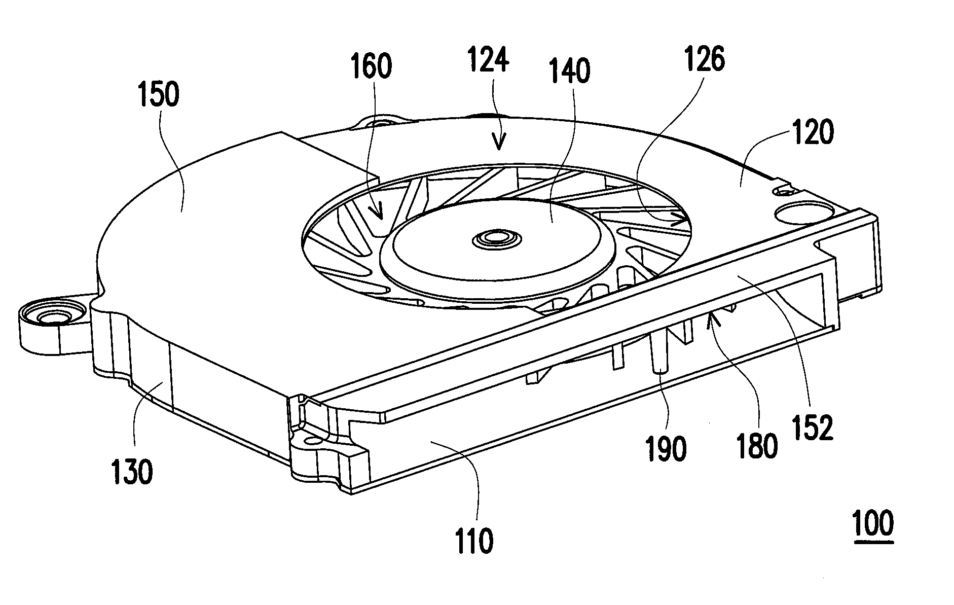
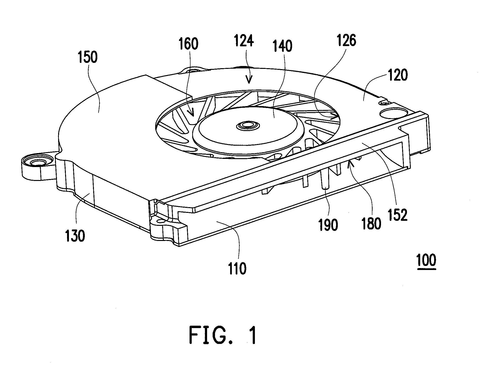
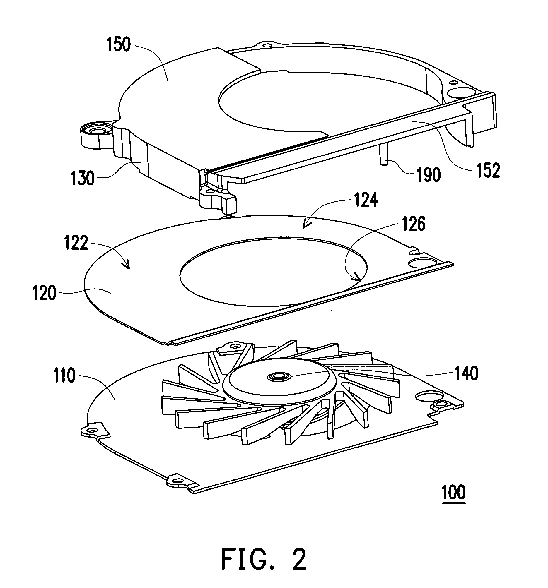
[0036]FIG. 1 is a schematic three-dimensional diagram of a fan module according to an embodiment of the invention and FIG. 2 is an exploded diagram of the fan module of FIG. 1. Referring to FIG. 1, a fan module 100 of the embodiment includes a bottom plate 110, a top cover 120, a sidewall 130, a heat-dissipating fan 140 and a housing 150. The sidewall 130 is assembled between the top cover 120 and the bottom plate 110, and the sidewall 130, the top cover 120 and the bottom plate 110 together form an accommodating space 160. The heat-dissipating fan 140 is disposed on the bottom plate 110 and located in the accommodating space 160. The housing 150 is stacked on the top cover 120, and the top cover 120 is located between the housing 150 and the bottom plate 110, in which the housing 150 and the top cover 120 can be assembled together through adhering, fastening or coating-injection. In other embodiments, the housing 150 can be assembled at the top cover 120 through other processes, wh...


PUM


Abstract

A fan module suitable for an electronic apparatus is provided. The fan module includes a bottom plate, a top cover. a sidewall, a heat-dissipating fan and a housing. The sidewall is assembled between the top cover and the bottom plate. The sidewall, the top cover and the bottom plate together form an accommodating space. The heat-dissipating fan is disposed on the bottom plate and located in the accommodating space. The housing is stacked on the top cover.

Description

CROSS-REFERENCE TO RELATED APPLICATION[0001]This application claims the priority benefits of U.S. provisional application Ser. No. 61 / 489,672, filed on May 24, 2011. The entirety of the above-mentioned patent applications is hereby incorporated by reference herein and made a part of this specification.BACKGROUND OF THE INVENTION[0002]1. Field of the Invention[0003]The invention generally relates to a fan module, and more particularly, to a fan module suitable for an electronic apparatus.[0004]2. Description of Related Art[0005]In order to meet the requirements of high speed, high performance, light-weight, small-size and low-profile of current electronic products, various portable electronic products have become the main stream in the market. As far as a notebook computer is concerned, because the notebook computer has only a limited space for receiving a heat dissipating system, how to enhance the heat dissipating efficiency in the limited space has become one of the research focus...

Claims


Application Information

Patent Timeline
IPC IPC(8): F04D1/00F04D29/40
CPCF04D29/4226G06F1/203F04D29/601F04D29/626F04D25/0613F04D17/16
Inventor WANG, HSUAN-CHENG
Owner COMPAL ELECTRONICS INC
Why Eureka
Try Eureka