Supercharge Your Innovation With Domain-Expert AI Agents!

Bend limiting stiffener and related methods

a technology which is applied in the direction of hose connection, manufacturing tools, mechanical equipment, etc., can solve the problems of high cost of installation of bend stiffener and limiter

Active Publication Date: 2012-12-06
DEEP DOWN INC
View PDF9 Cites 38 Cited by
  • Summary
  • Abstract
  • Description
  • Claims
  • Application Information

AI Technical Summary

Benefits of technology

[0009]In other aspects, embodiments disclosed herein relate to a method of inhibiting bending of a flexible pipe, the method including installing at least two bend limit...

Problems solved by technology

The installation of bend stiffeners and limiters may be very costly, as current technology allows for the units to be installed only during the umbilical manufacturing process.

Method used


Image

  • Bend limiting stiffener and related methods
  • Bend limiting stiffener and related methods
  • Bend limiting stiffener and related methods

Examples


Embodiment Construction

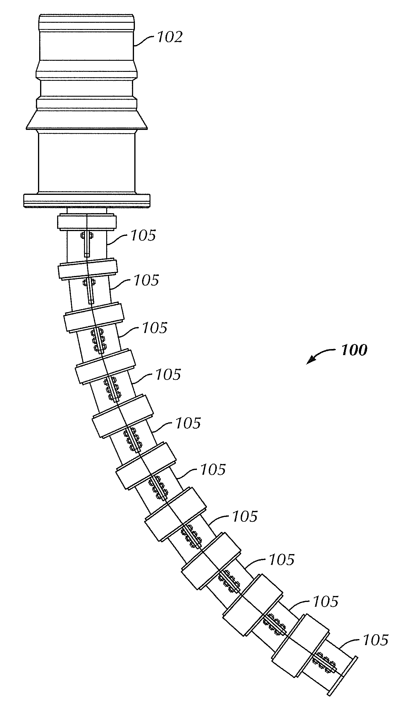
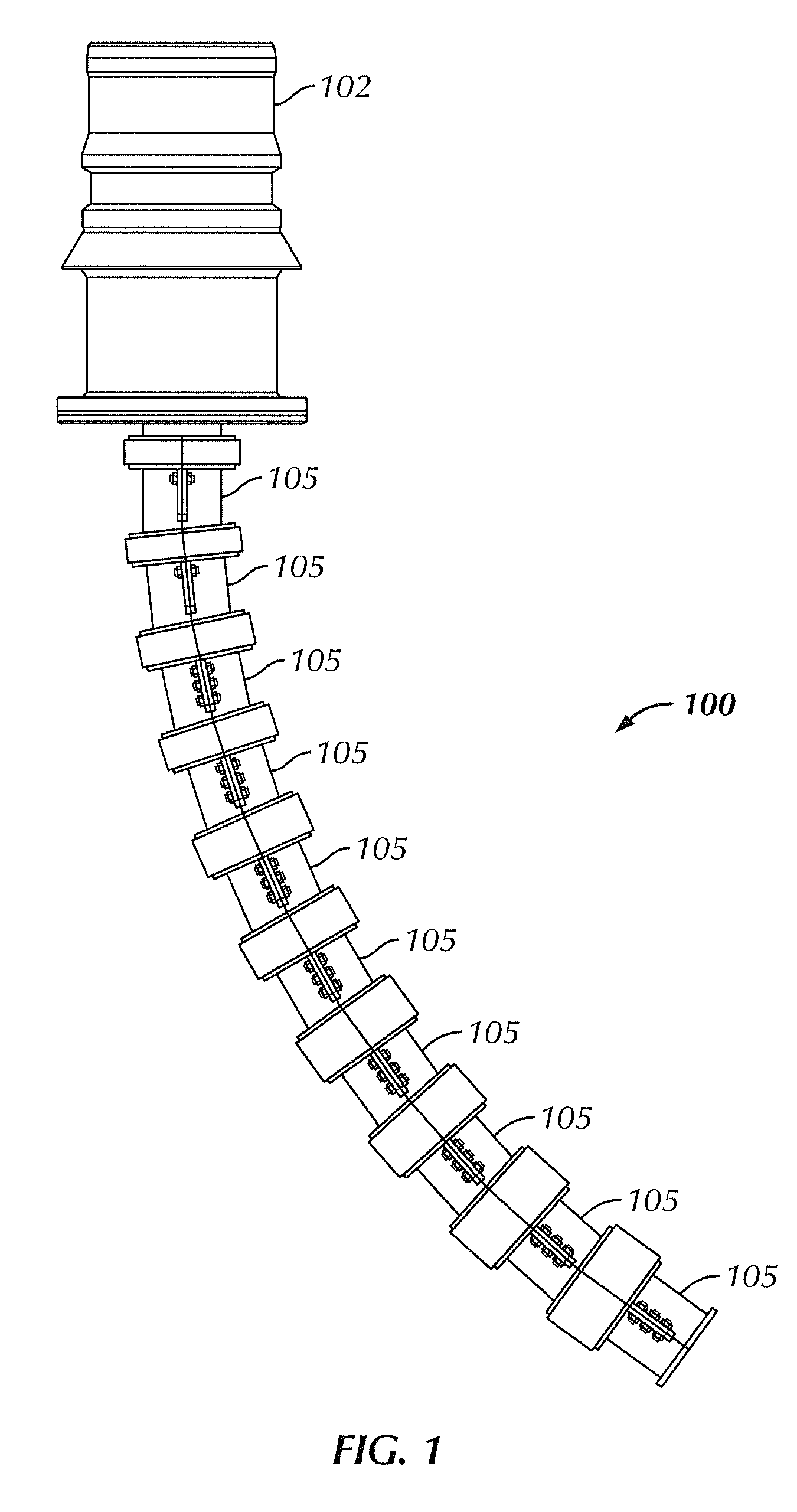
[0015]In one aspect, embodiments disclosed herein relate to a bend limiter with multiple stiffeners incorporated therein, or a bend limiting stiffener. The bend limiting stiffener may be used on umbilicals and other flexible pipes to resist bending while also limiting the amount of bend radius of the umbilical or flexible pipe. Referring to FIG. 1, a perspective view of a bend limiting stiffener 100 in accordance with one or more embodiments of the present disclosure is shown. The bend limiting stiffener 100 includes a series of individual bend limiter units 105 coupled together and installed onto an umbilical or flexible pipe (not shown). The umbilical or flexible pipe may extend from a termination point or connector 102, which may ultimately terminate in a rigid structure (not shown), such as a rig structure or equipment on the rig structure.

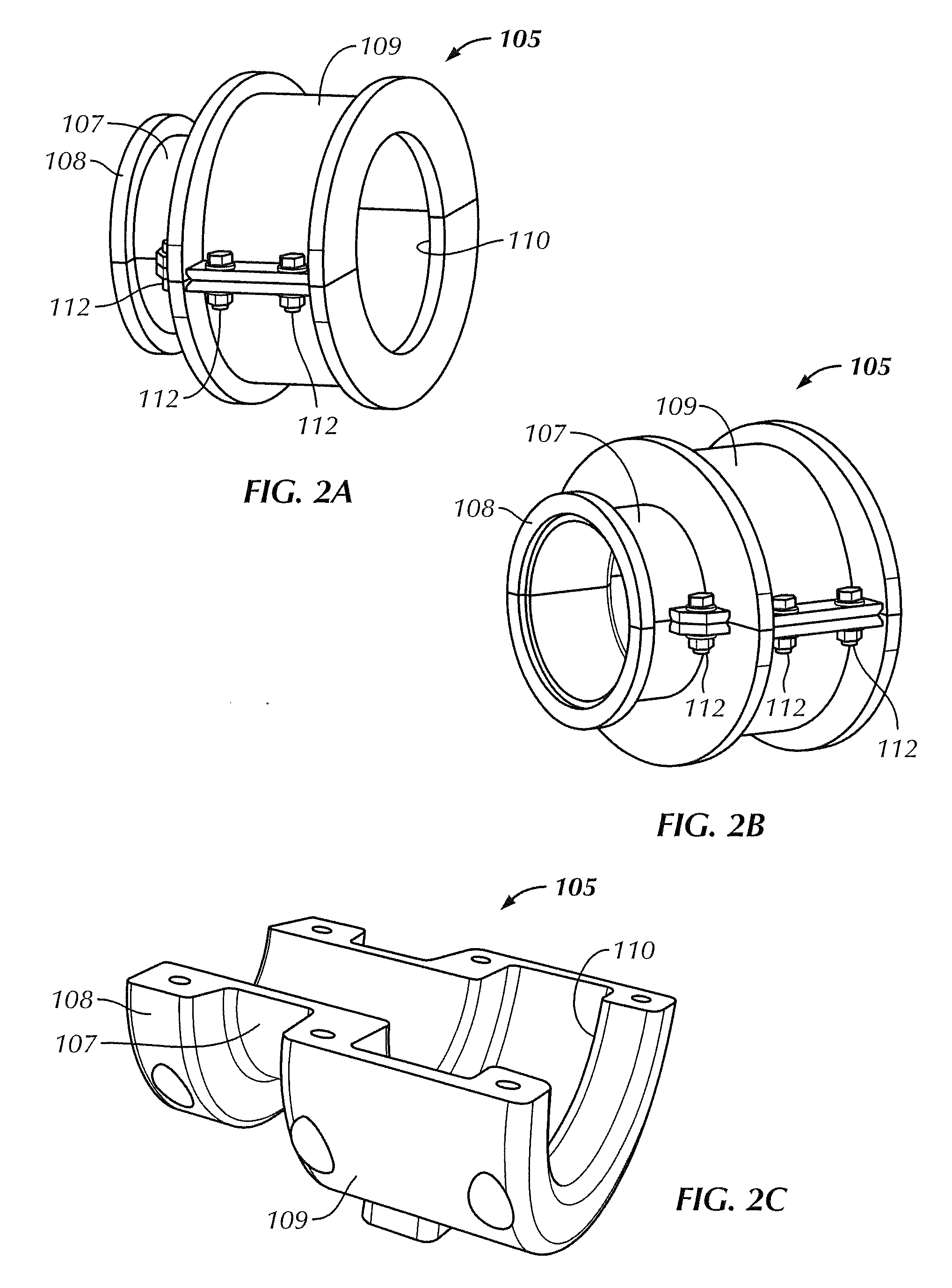
[0016]Referring now to FIGS. 2A and 2B, perspective views of an individual bend limiter unit 105 in accordance with one or more embodiments o...


PUM

PropertyMeasurementUnit
Fractionaaaaaaaaaa
Thicknessaaaaaaaaaa
Angleaaaaaaaaaa

Abstract

A bend restrictor device includes at least two bend limiter units coupled together and having at least one stiffness ring disposed therebetween.

Description

CROSS-REFERENCE TO RELATED APPLICATIONS[0001]This application claims priority under 35 U.S.C. §119(e) to U.S. Provisional Application Ser. No. 61 / 492,162 filed on Jun. 1, 2011, which is hereby incorporated by reference in its entirety.BACKGROUND[0002]1. Field of the Disclosure[0003]Embodiments disclosed herein relate generally to bend restrictor devices for flexible pipes and umbilicals. In particular, embodiments disclosed herein relate to a bend limiting stiffener installed on umbilicals and flexible pipes.[0004]2. Background Art[0005]Flexible pipes, flowlines, power cables, and umbilicals are usually connected to a rigid structure such as a subsea riser base, pipeline end manifold (PLEM), wellhead or other structure. To prevent these pipes from overbending at the interface between flexible and rigid structures, bending restrictors may be installed on the pipe. Bending restrictors, or bend limiters, are devices used where static (or quasi static) loads act on a pipe, while bend st...

Claims


Application Information

Patent Timeline
IPC IPC(8): F16L57/02B23P11/00
CPCF16L57/02Y10T29/4984F16L35/00F16L1/123E21B17/017
Inventor SMITH, RONHUNT, JEFF
Owner DEEP DOWN INC
Features
  • R&D
  • Intellectual Property
  • Life Sciences
  • Materials
  • Tech Scout
  • Unparalleled Data Quality
  • Higher Quality Content
  • 60% Fewer Hallucinations
Learn More