
Exhaust gas aftertreatment device and method for a gasoline engine

a technology of exhaust gas aftertreatment and gasoline engine, which is applied in the direction of machines/engines, mechanical devices, surface coverings, etc., can solve the problems of internal combustion engines with spark ignition, internal combustion engines producing soot particles during operation, and reducing the release of soot particles and pollution of ambient air

Active Publication Date: 2012-12-06
FORD GLOBAL TECH LLC
View PDF18 Cites 30 Cited by
  • Summary
  • Abstract
  • Description
  • Claims
  • Application Information

AI Technical Summary

Benefits of technology

The patent text describes an exhaust gas aftertreatment device for gasoline engines that integrates the function of a particle filter with the function of a three-way catalyst. The device removes soot from the exhaust gas and converts emissions in the exhaust gas using a catalyst material coated on the filter walls. The technical effect of this invention is to provide a single exhaust aftertreatment device that reduces the resistance posed by the particle filter to the throughflow of the exhaust gas, while also reducing emissions and fuel consumption.

Problems solved by technology

Internal combustion engines produce soot during the combustion process.
However, internal combustion engines with spark ignition, in particular gasoline engines with direct injection, produce soot particles during operation which may enter the ambient air with the exhaust gas.
Such a particle filter may be an additional component part having a corresponding spatial requirement and additional costs.
However, the inventors herein have recognized a few issues with the above approaches.
For example, it has been found that the insertion of the catalytic coating in the filter walls of the particle filter (GPF) leads to impaired starting behavior compared to conventional three-way catalysts (TWCs).
It would also be possible to improve starting behavior by way of an increased noble metal content of the catalyst material, but this would increase costs.

Method used


Image

  • Exhaust gas aftertreatment device and method for a gasoline engine
  • Exhaust gas aftertreatment device and method for a gasoline engine
  • Exhaust gas aftertreatment device and method for a gasoline engine

Examples


Embodiment Construction

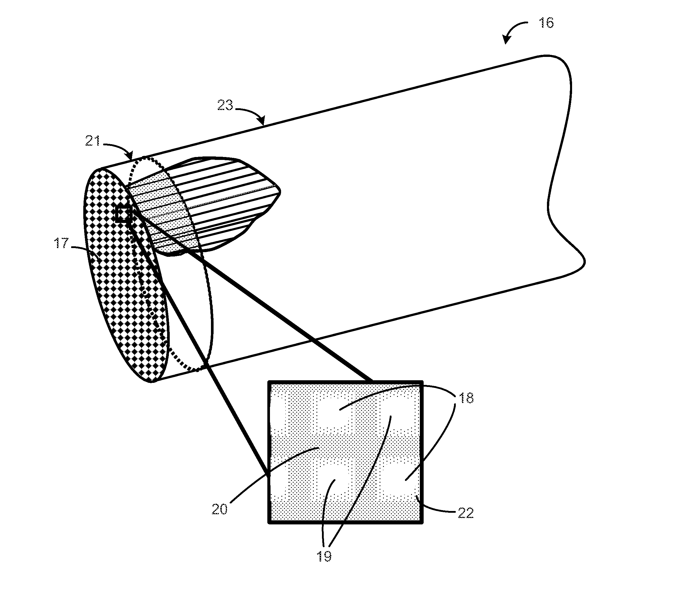
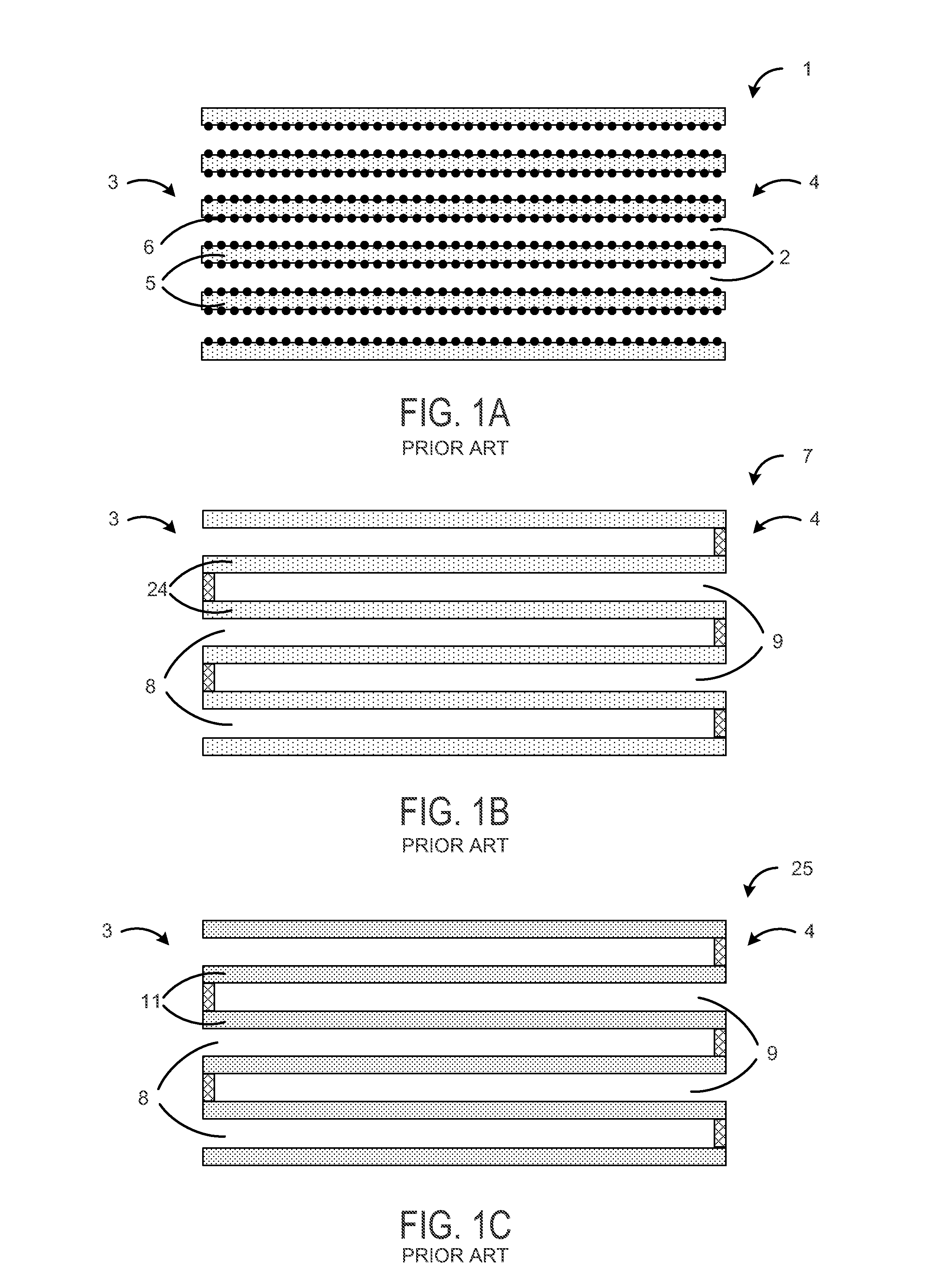
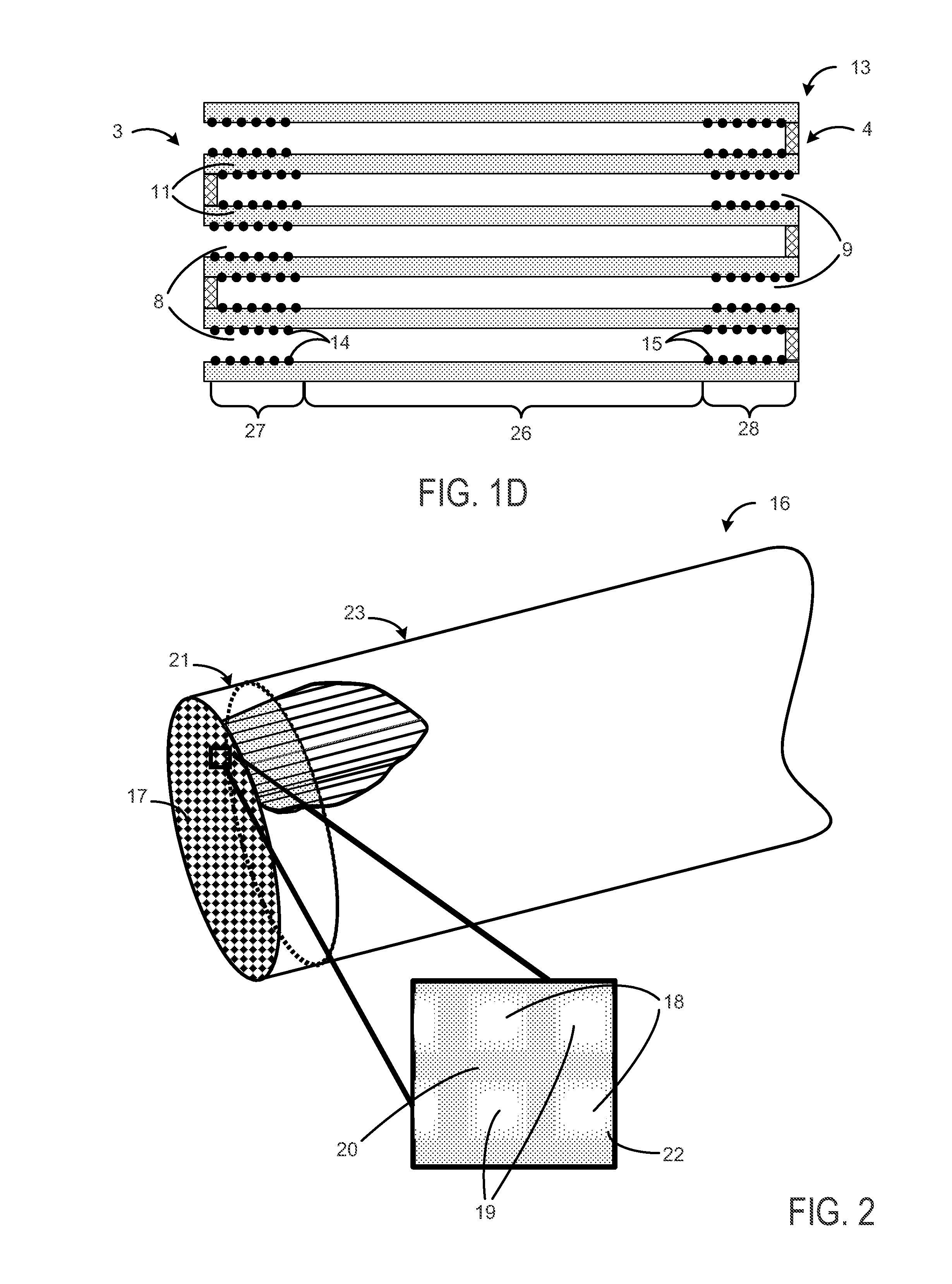
[0016]The aftertreatment device of the present disclosure includes a filter body, which for example may be comprised of a ceramic material, the substrate, and which for example comprises exhaust gas ducts extending parallel to one another. The partition walls between adjacent exhaust gas ducts are formed as porous filter walls for retaining soot contained in the exhaust gas and are passed through by the exhaust gas. For this purpose, the exhaust gas ducts are closed alternately for example at their outflow-side or inflow-side ends so that the exhaust gas passing from the inflow-side end section to the outflow-side end section of the filter body flows through the filter walls. The filter body is thus formed as a particle filter for the removal of soot from the exhaust gas flow of the gasoline engine.

[0017]In accordance with the disclosure the porous filter walls contain a catalyst material of a three-way catalyst, that is to say a catalyst material for obtaining the effect of a three...


PUM


Abstract

Embodiments for an exhaust gas aftertreatment device are provided. In one example, an exhaust gas aftertreatment device for a gasoline engine comprises a filter body with porous filter walls through which exhaust gas flows to remove soot, the porous filter walls containing a first catalyst material and having a coating of a second catalyst material on partial areas of the filter walls. In this way, a particulate filter and catalyst may be provided in a common aftertreatment device.

Description

RELATED APPLICATIONS[0001]The present application claims priority to German Patent Application Number 102011050788.4, filed on Jun. 1, 2011, the entire contents of which are hereby incorporated by reference for all purposes.FIELD[0002]The disclosure relates to an exhaust gas aftertreatment device for a gasoline engine and to an exhaust gas aftertreatment method for a gasoline engine.BACKGROUND AND SUMMARY[0003]Internal combustion engines produce soot during the combustion process. This is known for diesel engines and has led to the development of corresponding soot filters and exhaust gas aftertreatment systems for diesel engines. However, internal combustion engines with spark ignition, in particular gasoline engines with direct injection, produce soot particles during operation which may enter the ambient air with the exhaust gas. Even though the amount of soot particles produced in gasoline engines is generally lower than in diesel engines, it is desirable to prevent or at least ...

Claims


Application Information

Patent Timeline
Patent Type & Authority Applications(United States)
IPC IPC(8): F01N3/035
CPCF01N3/101Y02T10/22F01N2510/0682F01N3/035Y02T10/12
Inventor SPRINGER, MORITZ KLAUSRUHLAND, HELMUT HANSLORENZ, THOMAS
Owner FORD GLOBAL TECH LLC
Learn More