

Heating apparatus, coating apparatus and heating method
a technology of coating apparatus and heating method, which is applied in the direction of muffle furnace, furnace, charge manipulation, etc., to achieve the effect of reliable formation
- Summary
- Abstract
- Description
- Claims
- Application Information
AI Technical Summary
Benefits of technology
Problems solved by technology
Method used
Image

Examples
Embodiment Construction
[0063]Hereinafter, one embodiment of the present invention will be described with reference to the accompanying drawings.
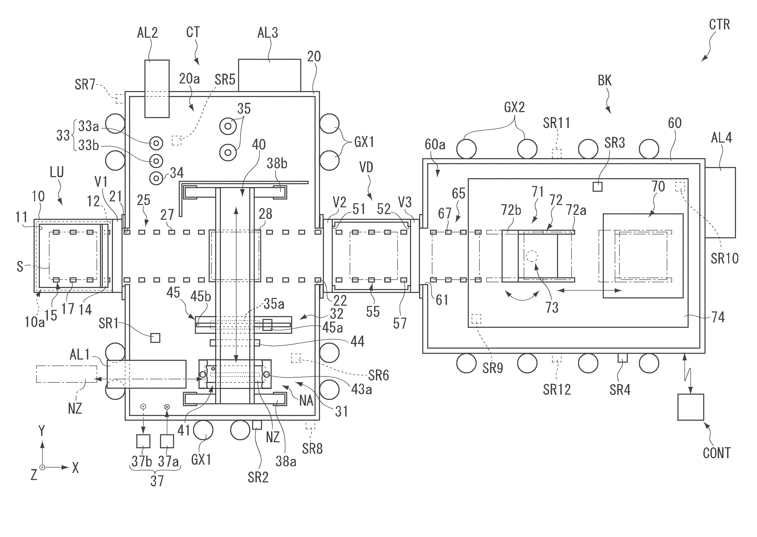
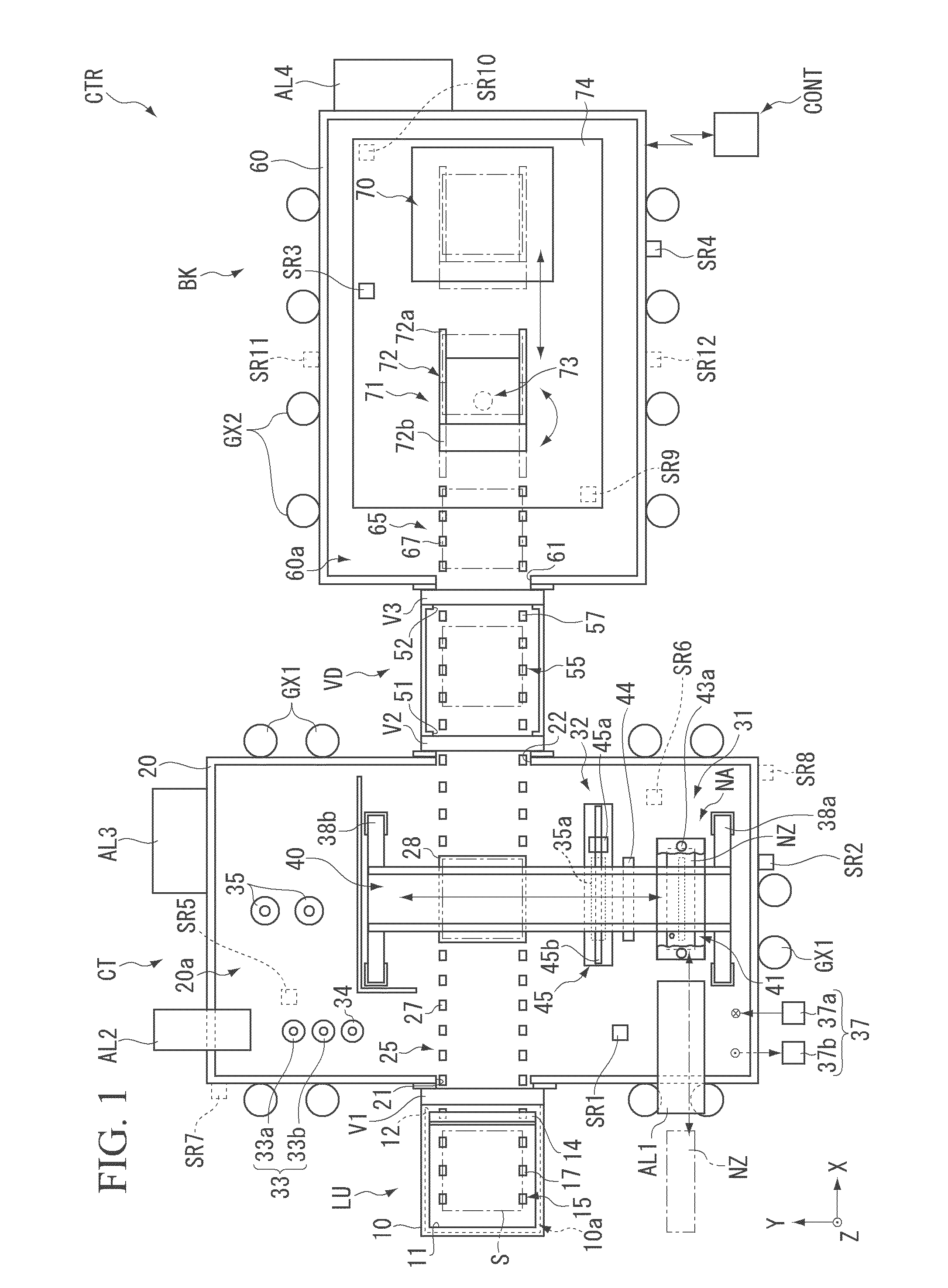
[0064]FIG. 1 is a schematic diagram showing a configuration of a coating apparatus CTR according to one embodiment of the present invention.
[0065]As shown in FIG. 1, the coating apparatus CTR is an apparatus which applies a liquid material to a substrate S. The coating apparatus CTR includes a substrate loading / unloading part LU, a coating part CT, a vacuum drying part VD, a baking part BK and a control part CONT.
[0066]The coating apparatus CTR is used, for example, by being disposed on a floor FL in a factory. The coating apparatus may have a configuration in which the coating apparatus is accommodated in one room, or a configuration in which the coating apparatus is divisionally accommodated in a plurality of rooms. In the coating apparatus CTR, the substrate loading / unloading part LU, the coating part CT, the vacuum drying part VD and the baking part BK are arr...
PUM
 Abstract
Description
Claims
Application Information