

Anti-dazzling optical laminate
a technology of optical laminates and optical laminates, applied in the field of anti-dazzling optical laminates, can solve problems such as difficulty in maintaining black color reproduction, and achieve the effects of improving black color reproduction, preventing glare, and improving contras
- Summary
- Abstract
- Description
- Claims
- Application Information
AI Technical Summary
Benefits of technology
Problems solved by technology
Method used
Image

Examples
example 1
Formation of Anti-Dazzling Layer
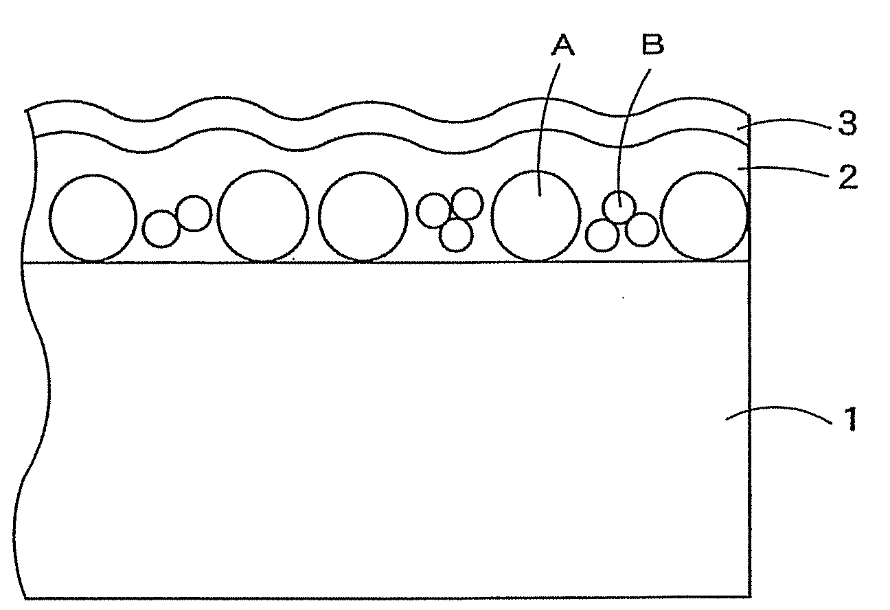
[0252]An 80 μm-thick triacetylcellulose film (TD80U, manufactured by Fuji Photo Film Co., Ltd.) was provided as a transparent base material. Composition 1 for an anti-dazzling layer was coated onto the transparent base material with a wire-wound rod for coating (Mayer's bar) #6, and the coated transparent base material was heat dried in an oven of 70° C. for one min to evaporate the solvent component. Thereafter, under nitrogen purge (oxygen concentration: not more than 200 ppm), ultraviolet light was applied at an exposure of 100 mJ to cure the coating film and thus to form an anti-dazzling optical laminate. The total thickness of the anti-dazzling layer on the base material was about 2.7 μm.
example 2
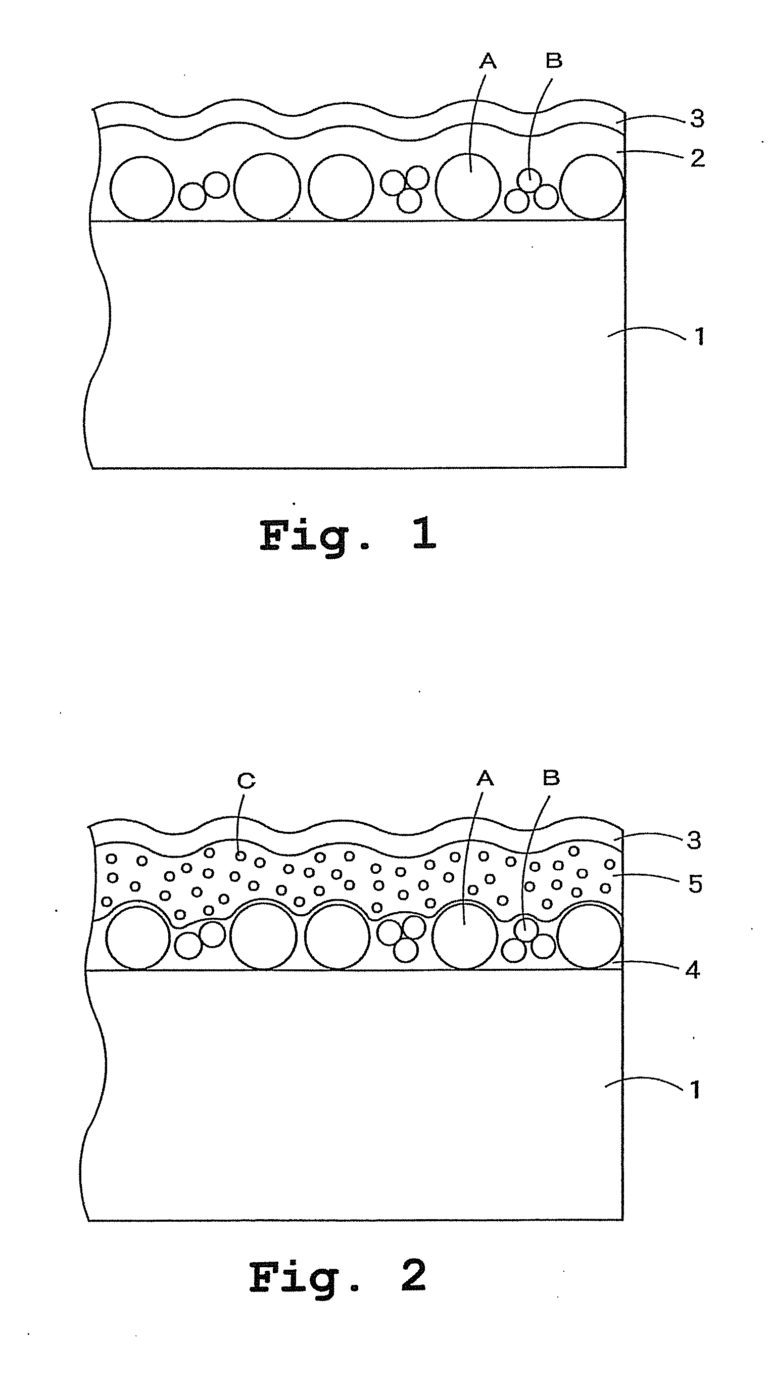
Formation of Substrate Concavoconvex Layer
[0253]An 80 μm-thick triacetate cellulose film (TD80U, manufactured by Fuji Photo Film Co., Ltd.) was provided as a transparent base material. Composition 4 for a substrate concavoconvex layer was coated onto the transparent base material with a wire-wound rod for coating (Mayer's bar) #14, and the coated transparent base material was heat dried in an oven of 70° C. for one min to evaporate the solvent component. Thereafter, ultraviolet light was applied at an exposure of 30 mJ to cure the coating film and thus to form a substrate concavoconvex layer.
Formation of Surface Modifying Layer
[0254]Composition 2 for a surface modifying layer was further coated onto the substrate concavoconvex layer with a wire-wound rod for coating (Mayer's bar) #10, and the coating was heat dried in an oven of 70° C. for one min to evaporate the solvent component. Thereafter, under nitrogen purge (oxygen concentration: not more than 200 ppm), ultraviolet light was...
example 3
Formation of Substrate Concavoconvex Layer
[0255]An 80 μm-thick triacetate cellulose film (TD80U, manufactured by Fuji Photo Film Co., Ltd.) was provided as a transparent base material. Composition 1 for a substrate concavoconvex layer was coated onto the transparent base material with a wire-wound rod for coating (Mayer's bar) #10, and the coated transparent base material was heat dried in an oven of 70° C. for one min to evaporate the solvent component. Thereafter, ultraviolet light was applied at an exposure of 30 mJ to cure the coating film and thus to form a substrate concavoconvex layer.
Formation of Surface Modifying Layer
[0256]Composition 2 for a surface modifying layer was further coated onto the substrate concavoconvex layer with a wire-wound rod for coating (Mayer's bar) #12, and the coating was heat dried in an oven of 70° C. for one min to evaporate the solvent component. Thereafter, under nitrogen purge (oxygen concentration: not more than 200 ppm), ultraviolet light was...
PUM
| Property | Measurement | Unit |
|---|---|---|
| Fraction | aaaaa | aaaaa |
| Fraction | aaaaa | aaaaa |
| Fraction | aaaaa | aaaaa |
Abstract
Description
Claims
Application Information