
Magnetic detection apparatus

a detection apparatus and magnetic technology, applied in the direction of magnetic measurement, instruments, manufacturing tools, etc., can solve the problems of deteriorating reliability of the output voltage of the detector, excessive injection pressure caused by injection molding, and excessive injection pressure applied to the detection element, so as to increase the output reliability of the detection element

Inactive Publication Date: 2012-12-06
DENSO CORP
View PDF0 Cites 18 Cited by
  • Summary
  • Abstract
  • Description
  • Claims
  • Application Information

AI Technical Summary

Benefits of technology

[0006]In view of the foregoing difficulties, it is an object of the present disclosure to provide a magnetic detection apparatus in which a characteristic of an output voltage is less likely to fluctuate when defining a position of a magnetoelectric transducer by forming a resin mold portion in an injection molding manner. It is another object of the present disclosure to provide a detection apparatus in which an output reliability of a detection element is increased, and a manufacturing method of the detection apparatus.
[0008]In the above apparatus, when forming the resin mold portion by injection molding, an injection pressure caused by resin injection is not applied to the IC package of the IC device. Thus, when defining the position of the magnetoelectric transducer by forming the resin mold portion in an injection molding manner, a characteristic of an output voltage of the IC device is less likely to fluctuate.
[0010]In the above apparatus, when forming the housing by injection molding, a penetration of the resin material of the housing to the cylindrical portion is suppressed by the cover. Thus, application of an injection pressure generated by the resin material of the housing is suppressed. Therefore, an output reliability of the detection element is increased.
[0012]In the above method, an injection pressure generated in the first injection molding and an injection pressure generated in the second injection molding are less likely to apply to the detection element. Therefore, an output reliability of the detection element is increased.

Problems solved by technology

However, when forming the casing by the first molding, an injection pressure caused by injection molding may be applied excessively to the detection element.
Similarly, when forming the housing by the second molding, an injection pressure caused by injection molding may be applied excessively to the detection element through the casing.
Thus, a reliability of an output voltage of the detector may be deteriorated.

Method used


Image

  • Magnetic detection apparatus
  • Magnetic detection apparatus
  • Magnetic detection apparatus

Examples


first embodiment

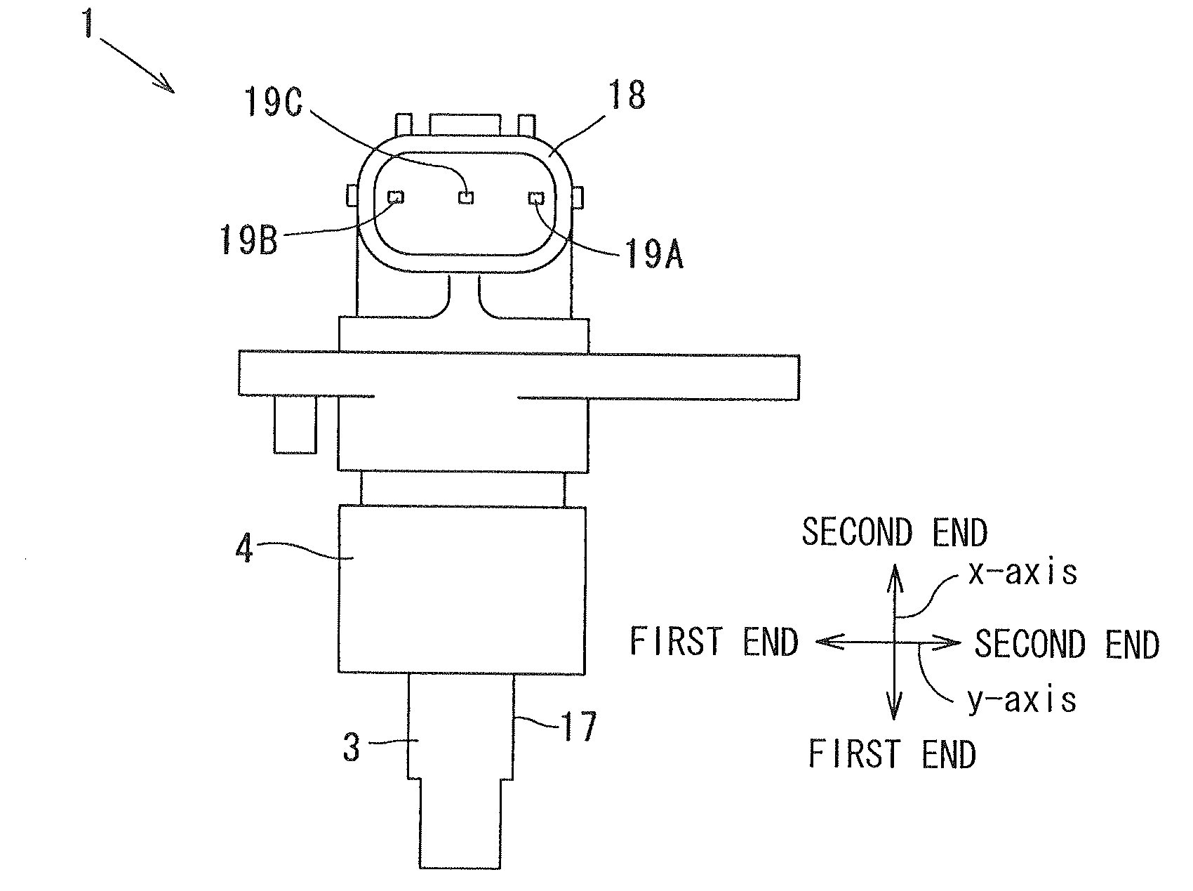
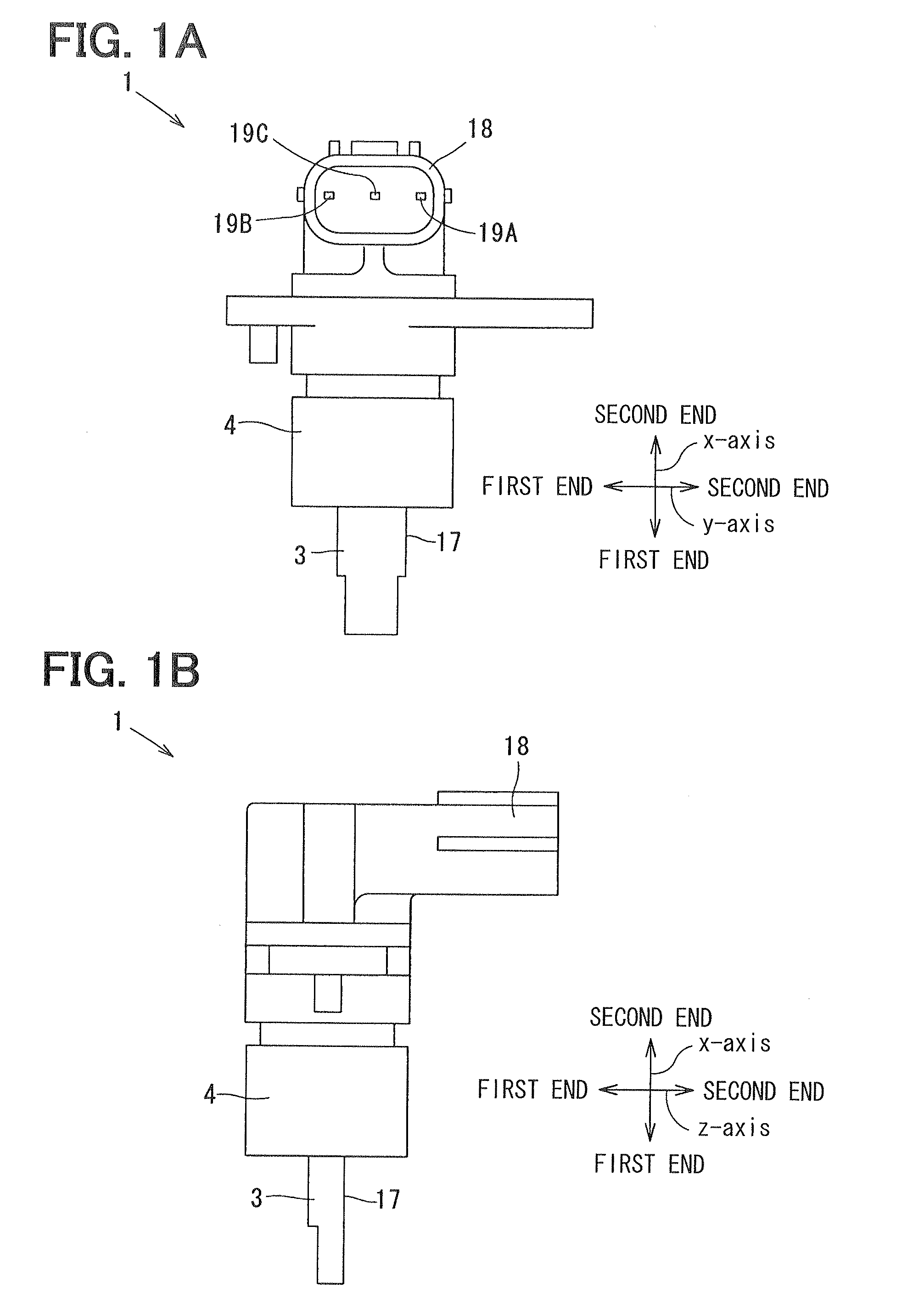
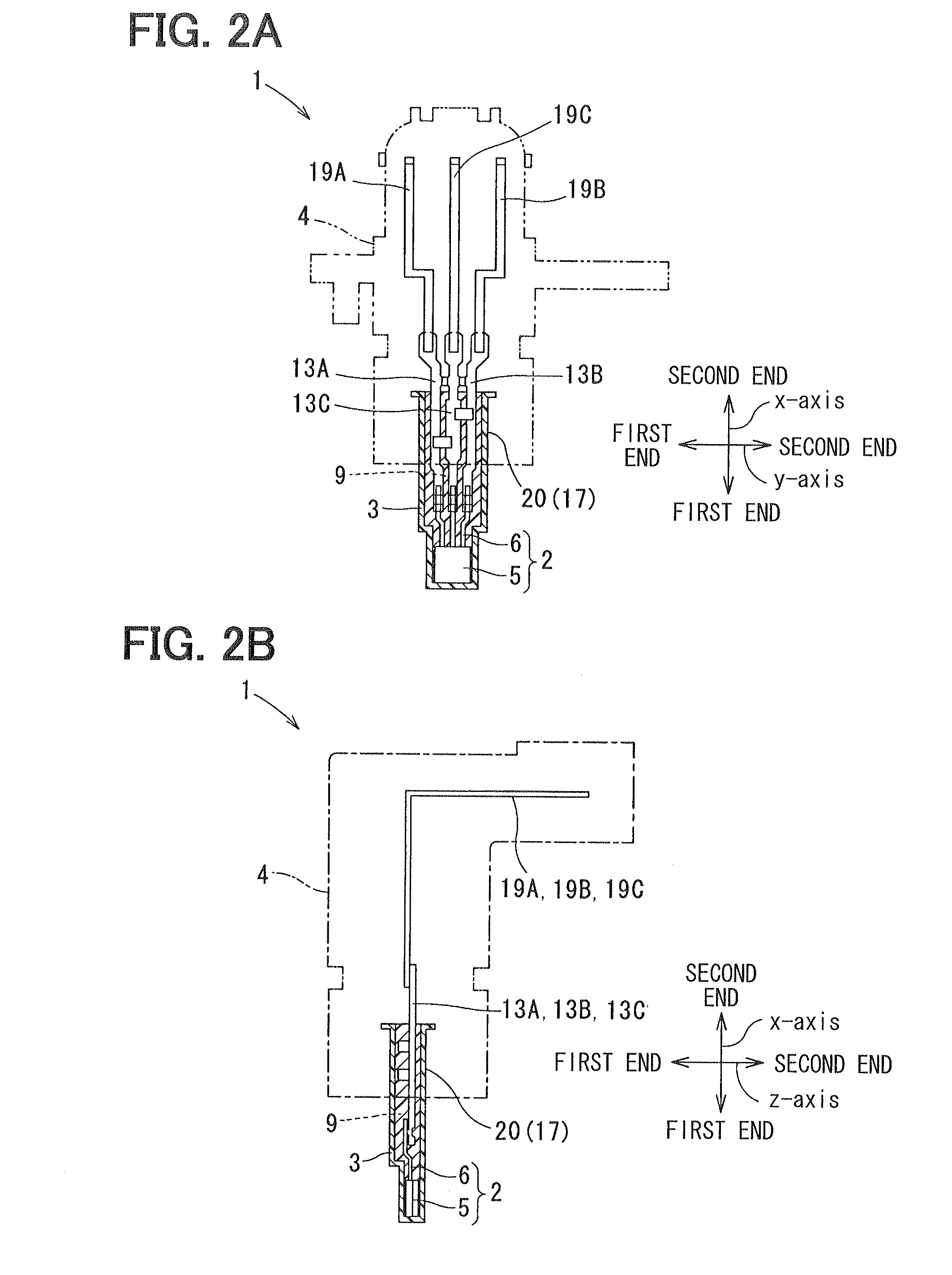
[0035]The magnetic detection apparatus 1 (hereinafter referred to as a detection apparatus) according to the first embodiment will be described with reference to FIGS. 1A to 3C. For example, the detection apparatus 1 includes a magnetoelectric transducer (not shown) such as a hall element, and a magnetic flux generator (not shown) such as a permanent magnet. When the magnetic flux generator rotates relatively around the magnetoelectric transducer or moves to have a linear displacement relative to the magnetoelectric transducer, a magnetic filed generated by the magnetic flux generator varies. The detection apparatus 1 detects a rotation angle or a linear displacement by combining the magnetic flux generator with the magnetoelectric transducer. That is, with a function of the magnetoelectric transducer, the detection apparatus detects a magnetic flux content corresponding to a rotation angle or linear displacement of the magnetic flux generator, and generates a voltage corresponding ...

second embodiment

[0061]The detection apparatus 1 according to the second embodiment will be described with reference to FIGS. 4A to 4D. In the detection apparatus 1 according to the second embodiment, the opening portion 10 of the casing 3 is covered by the lid 22. The lid 22 may be made of, for example, resin material similar to the resin material of the casing 3. The lid 22 has three through holes 23 corresponding to the extension terminals 13A to 13C. The extension terminals 13A to 13C separately penetrate the respective through holes 23. Further, the extension terminal 13C has the stopper 24 to engage with the lid 22 when the extension terminals 13A to 13C penetrate the through holes 23.

[0062]After the lid 22 is engaged with the extension terminal 13C by the stopper 24, the lid 22 is integrated with the casing 3 by thermal caulking to cover the opening portion 10 of the casing 3. The casing 3 has a thermal caulking portion 25 at the second end side of the protruding portion 16 in the x-axis dire...

third embodiment

[0063]The detection apparatus 1 according to the third embodiment will be described with reference to FIGS. 5A and 5B. The detection apparatus 1 according to the third embodiment includes the sub assembly 27, which includes the insert components 26. The insert components 26 include the IC device 2 other than the IC package 5, the extension terminals 13A to 13C, and the capacitors 14, which are molded integrally by injection molding. The sub assembly 27 is housed in the housing space 9 of the casing 3, and then, the resin mold portion 4 is formed on the first part of the outside surface 17 of the casing 3.

[0064]Under the above-described configuration, the positions of the extension terminals 13A to 13C and the positions of the capacitors 14 are preliminarily defined and stabilized in the sub assembly 27. Then, the sub assembly 27 is housed in the casing 3 so that the IC package 5 is contacted with the sub contact regions LO to L4.

[0065]Then, the resin mold portion 4 is formed on the ...


PUM

PropertyMeasurementUnit
diameteraaaaaaaaaa
injection pressureaaaaaaaaaa
output voltageaaaaaaaaaa

Abstract

A magnetic detection apparatus includes an IC device, a casing defining a housing space of the IC device, and a resin mold portion arranged on a first part of an outside surface of the casing. The IC device includes an IC package having a built-in magnetoelectric transducer, and lead wires. The housing space is defined by a second part of an inner wall of the casing. A predetermined portion of the second part of the inner wall is defined as a contact region, with which the IC device contacts. The resin mold portion is arranged other than a predetermined portion of a second part of the outside surface corresponding to the contact region. A position of the magnetoelectric transducer is determined by positions of the contact region and the resin mold portion.

Description

CROSS REFERENCE TO RELATED APPLICATIONS[0001]This application is based on Japanese Patent Applications No. 2011-125465 filed on Jun. 3, 2011, and No. 2011-173830 filed on Aug. 9, 2011, the disclosures of which are incorporated herein by reference.TECHNICAL FIELD[0002]The present disclosure relates to a magnetic detection apparatus having a magnetoelectric transducer such as a hall element.BACKGROUND[0003]Conventionally, a magnetic detection apparatus having a magnetoelectric transducer such as a hall element is used for detecting a rotation angle or a linear displacement. As disclosed in JP-A-2004-004114 (which corresponds to U.S. Pat. No. 6,407,543), a magnetic detection apparatus includes an integrated circuit (IC) device molded with resin material by injection molding. The IC device includes an IC package that is placed inside of the IC device. In the IC package, a magnetoelectric transducer and processing circuits such as an amplification circuit are built in. A position of the ...

Claims


Application Information

Patent Timeline
Patent Type & Authority Applications(United States)
IPC IPC(8): G01R33/02B29C45/14
CPCG01D5/145G01D11/245G01R33/07
Inventor MIZUTANI, AKITOSHIKOUNO, NAOAKIHONDA, HITOMITAKIGUCHI, TOMOYUKI
Owner DENSO CORP
Learn More