Hardened wave-guide antenna

a waveguide antenna and hardened technology, applied in the direction of disturbance protection, differential interacting antenna combinations, radiating element structural forms, etc., can solve the problems of unprotected antennas, damaged by vehicle washes, and the burden on users of mobile radio equipment today, so as to reduce aperture and broad band performance

Active Publication Date: 2012-12-06
ELTA SYST LTD
View PDF8 Cites 6 Cited by
  • Summary
  • Abstract
  • Description
  • Claims
  • Application Information

AI Technical Summary

Benefits of technology

[0009]The present invention partially eliminates disadvantages of cited reference techniques and provides a novel antenna element that is substantially covert and difficult to detect and vandalize.
[0025]The antenna element according to the present invention may be efficiently manufactured. The printed circuit part of the antenna (e.g., exciter) can, for example, be manufactured by using printed circuit techniques.
[0026]The installation of the antenna element and antenna array of the present invention is relatively quick and easy and can be accomplished without substantial altering a vehicle in which it is to be installed.
[0027]The antenna element according to the present invention is of durable and reliable construction.
[0028]The antenna element according to the present invention may be readily conformed to complexly shaped surfaces and contours of a mounting platform. In particular, it can be readily conformable to a car or other structures.

Problems solved by technology

For example, a whip antenna must be mounted on an exterior surface of the vehicle, so that the antenna is unprotected from the weather, and may for example, be damaged by vehicle washes, unless temporarily removed.
The user of mobile radio equipment is often plagued today by the problem of vandalism of car radio antennas and burglary of the equipment.

Method used


Image

  • Hardened wave-guide antenna
  • Hardened wave-guide antenna
  • Hardened wave-guide antenna

Examples


Embodiment Construction

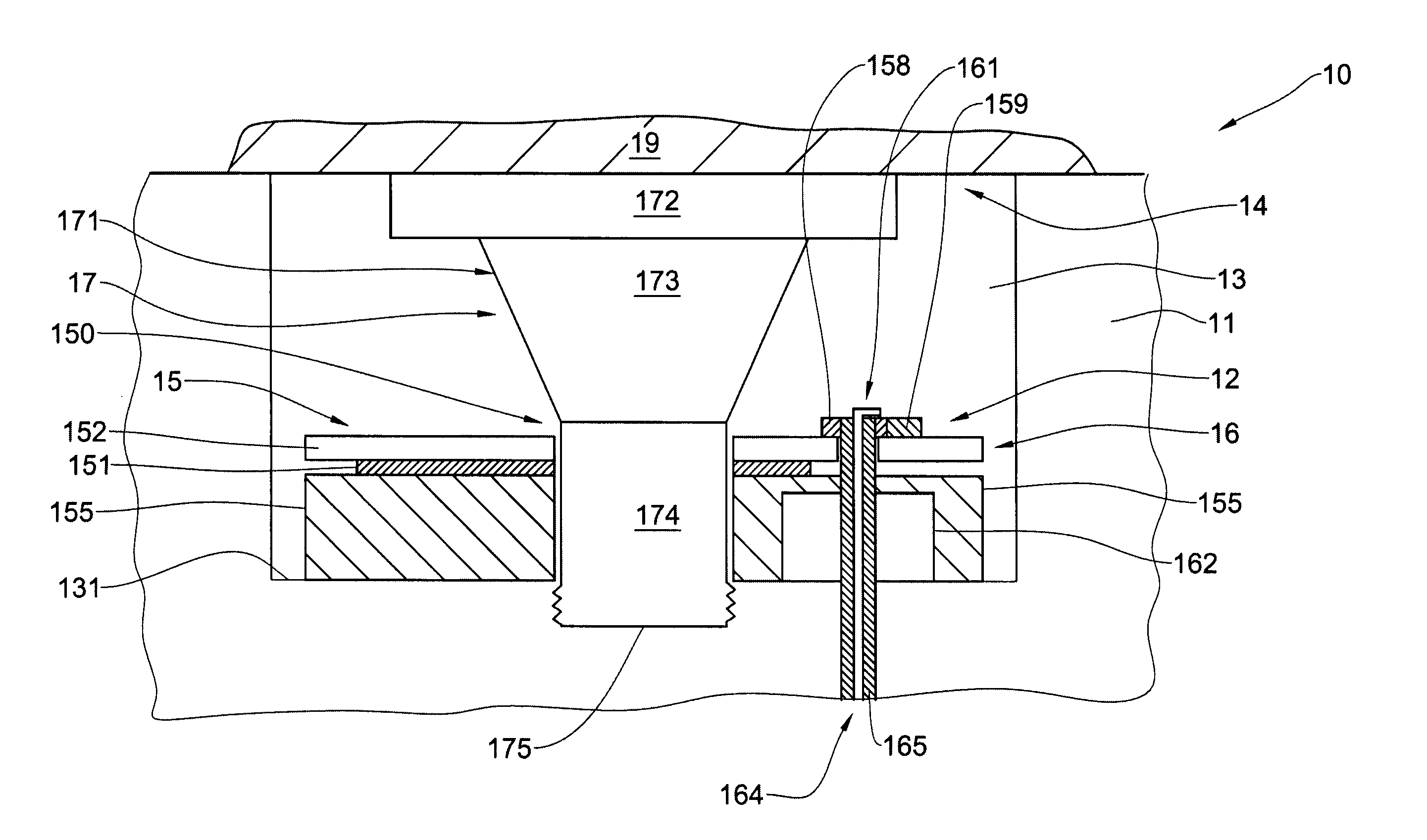
[0055]The principles of the antenna according to the present invention may be better understood with reference to the drawings and the accompanying description, wherein like reference numerals have been used throughout to designate identical elements. It being understood that these drawings which are not necessarily to scale, are given for illustrative purposes only and are not intended to limit the scope of the invention. Examples of constructions, materials, dimensions, and manufacturing processes are provided for selected elements. Those versed in the art should appreciate that many of the examples provided have suitable alternatives which may be utilized.

[0056]Referring now to the drawings, FIG. 1 illustrates a schematic side cross-sectional fragmentary view of an antenna element 10, according to one embodiment of the present invention. The antenna element 10 includes a waveguide 11 having a cavity 13 and configured for operating in a below-cutoff mode. The antenna element 10 al...


PUM


Abstract

An antenna element and a phased array antenna including a plurality of such antenna elements are described. The antenna element includes a waveguide configured for operating in a below-cutoff mode and having a cavity, an exciter configured for exciting the waveguide, and a shield. The shield includes a holder arranged within the cavity, and a front plate mounted on the holder and disposed over at least a part of the exciter.

Description

FIELD OF THE INVENTION[0001]This invention relates to radio-frequency antenna structures and, more particularly, to low-profile hardened wave-guide antennas.BACKGROUND OF THE INVENTION[0002]Mobile radio communications presently mainly rely on conventional whip-type antennas mounted to the roof, hood, or trunk of a motor vehicle. Although whip antennas generally provide acceptable mobile communications performance, they have a number of disadvantages. For example, a whip antenna must be mounted on an exterior surface of the vehicle, so that the antenna is unprotected from the weather, and may for example, be damaged by vehicle washes, unless temporarily removed.[0003]The user of mobile radio equipment is often plagued today by the problem of vandalism of car radio antennas and burglary of the equipment. Indeed, the presence of a whip antenna on the exterior of a car is a good clue to thieves that a radio, telephone transceiver or other equipment is installed within the vehicle.[0004]...

Claims


Application Information

Patent Timeline
Patent Type & Authority Applications(United States)
IPC IPC(8): H01Q13/00H01Q21/29
CPCH01Q1/002H01Q1/32H01Q1/38H01Q1/42H01Q21/061H01Q9/0457H01Q9/0464H01Q13/18H01Q3/26H01Q13/08
Inventor MISHAN, SHAULBAUER, REUVEN
Owner ELTA SYST LTD
Why Eureka
Try Eureka