Fixed structure for LED strip and LCD

Active Publication Date: 2012-12-06
TCL CHINA STAR OPTOELECTRONICS TECH CO LTD
View PDF2 Cites 12 Cited by
  • Summary
  • Abstract
  • Description
  • Claims
  • Application Information

AI Technical Summary

Benefits of technology

[0005]The main object of this invention is to provide an LED strip fixed structure and an LCD. The p

Problems solved by technology

When in use of the LED lamp backlight device, the heat emitted from the LED is diffused to the direction of the aluminum extrusion to the back panel, however, this heat dissipation method can not effectively diffuse the heat emitted from the LED to its side, thereby leading to the obvious temperature rise at the part of an LCD panel near the LED lamp.
The temperature rise not only reduces the luminous efficiency of the LED lamp, but also causes uneven temp

Method used


Image

  • Fixed structure for LED strip and LCD
  • Fixed structure for LED strip and LCD
  • Fixed structure for LED strip and LCD

Examples


Example

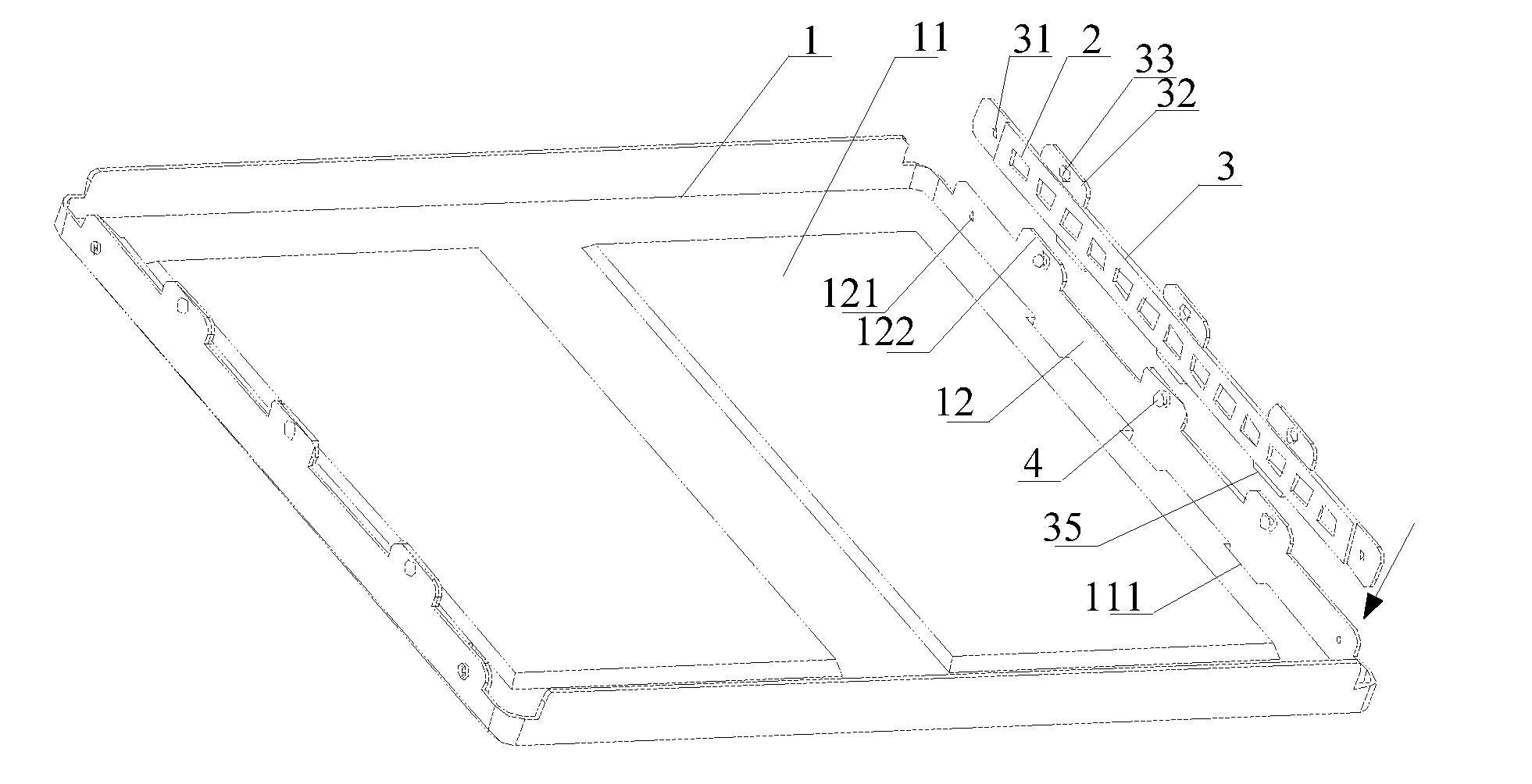
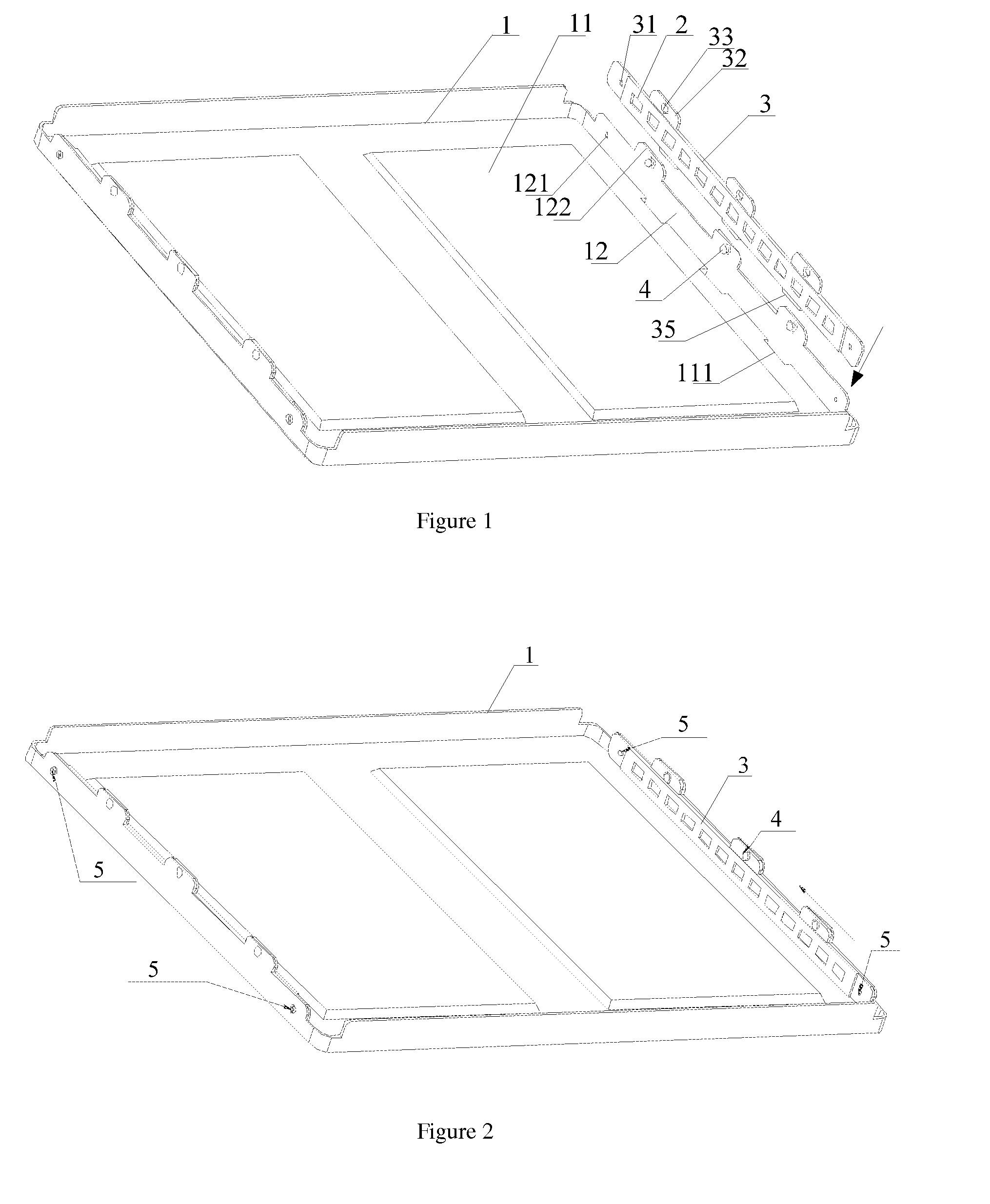
[0050]When installing, similar to the first embodiment as above, however in the second embodiment, insert the fixed element 3 into the back panel 1 in the arrow direction as shown in FIG. 1 and then immediately lock a screw 5 instead of pushing the fixed element 3 in the arrow direction as shown in FIG. 2.

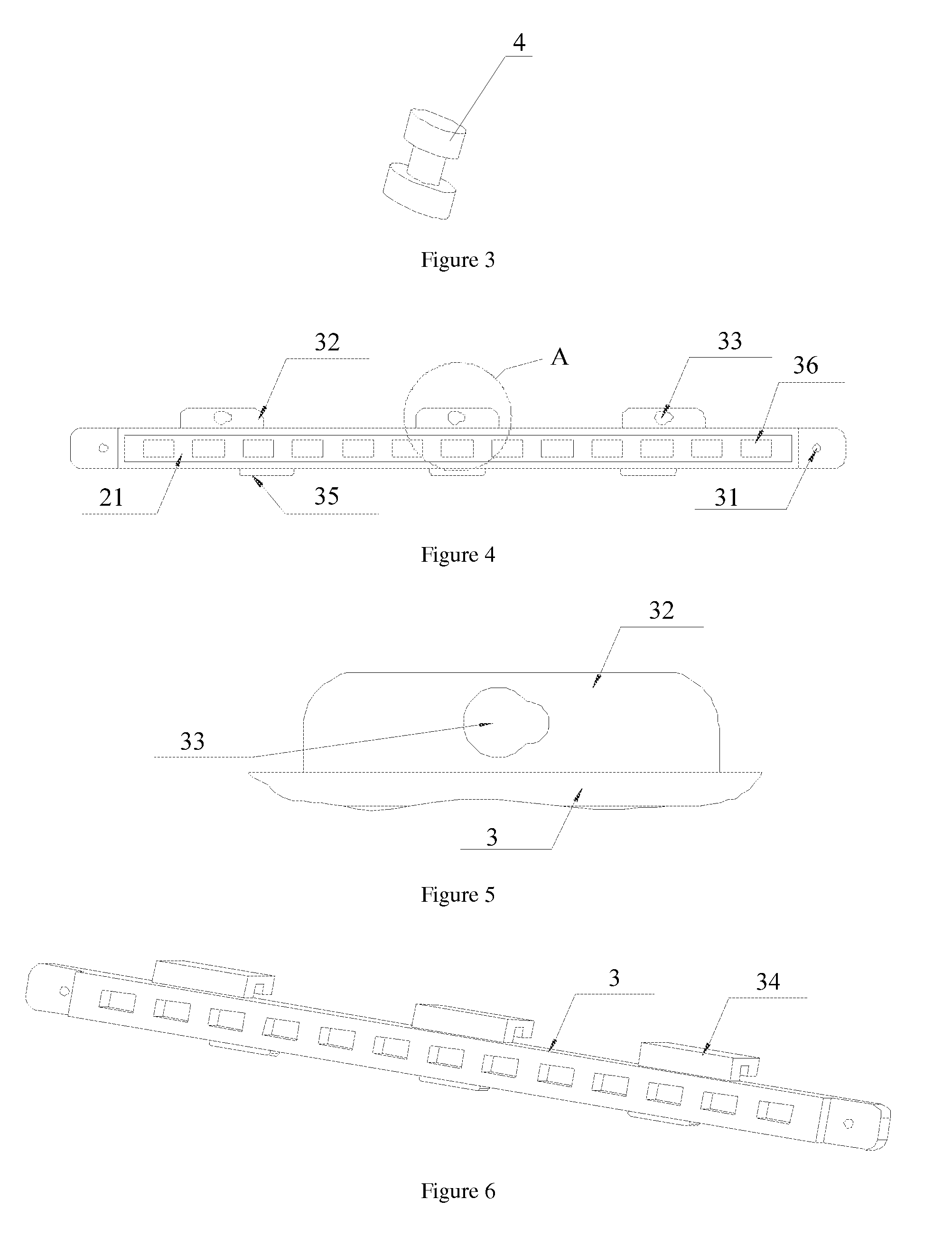
[0051]Please refer to FIG. 7, FIG. 8, FIG. 9, FIG. 10 and FIG. 11 altogether. FIG. 7 is the structure decomposition diagram of an embodiment of an LCD in this invention. The LCD of the embodiment in this invention includes a back panel 1, a LED strip 2, a fixed element 3, a front frame 6, a panel 7, a rubber frame 8, an optical film 9 and an LGP 10. A groove is arranged on the fixed element 3. The LED strip 2 is accommodated in the groove on the fixed element 3; the fixed element 3 is fixedly connected with the back panel 1 with a rivet bolt 4 and a screw 5. FIG. 8 is the front view diagram of an embodiment of the LCD in this invention; FIG. 9 is the cross section diagram in the A-...


PUM


Abstract

This invention relates to an LED strip fixed structure and an LCD, wherein the LED strip fixed structure includes a back panel, an LED strip and a strip fixed element, a groove used for accommodating the LED strip is formed on the strip fixed element, and light holes used for accommodating LEDs on the LED strip are formed in the groove; the fixed element is used for containing the LED strip, and is fixedly connected with the back panel. In this invention, the fixed element for accommodating the LED strip is fixed on the side wall of the back panel, so as to increase the heat dissipation channel of the LED strip; instead of arranging heat dissipation aluminum extrusion between the LED strip and the back panel, and so as to reduce the quantity of connecting pieces such as connecting screws. This invention improves the effect of heat dissipation at the backlight part of the LCD, and meanwhile simplifies the installation structure of the LED strip and lowers the cost.

Description

FIELD OF THE INVENTION[0001]This invention relates to the technical field of (liquid crystal display) LCDs, in particular to a fixed structure for an LED (Light Emitting Diode) strip and an LCD.BACKGROUND OF THE INVENTION[0002]An LCD is a panel display device for displaying the image by utilizing the liquid crystal, has the advantages of lightness and thinness, lower driving voltage and lower power consumption compared with other display devices, and therefore is widely applied in the whole industry. Whereas, an LCD panel of the LCD can not automatically emit light, and a backlight source assembly providing artificial light independently is needed.[0003]An LED lamp serves as the backlight source, and the backlight source adopts two types: a side backlight and a bottom backlight, and compared with a cold cathode fluorescent lamp (CCFL), the LED lamp has the advantages of energy conservation, long service life and small size, and is regarded as the development tendency of the LCD in f...

Claims


Application Information

Patent Timeline
IPC IPC(8): G02F1/13357F21V7/22
CPCG02F1/133615G02F2001/133628G02B6/009G02B6/0068G02F2201/46G02F1/133628
Inventor ZHOU, GEGE
Owner TCL CHINA STAR OPTOELECTRONICS TECH CO LTD
Why Eureka
Try Eureka