Light source device and display device

a technology of light source and display device, which is applied in the direction of lighting and heating apparatus, instruments, mechanical equipment, etc., can solve the problems of reducing the flexibility of disposition and structure of light source, ptls 1 and 2, and displaced light guide plate, so as to reduce the intensity of light emitted to the front, reduce the intensity of light emitted, and minimize the effect of non-uniformization

Inactive Publication Date: 2012-12-06
SHARP KK
View PDF10 Cites 13 Cited by
  • Summary
  • Abstract
  • Description
  • Claims
  • Application Information

AI Technical Summary

Benefits of technology

[0025]Because the light source device of the present invention has the configuration that the light that is projected onto the portions in the vicinity of the locking member is higher in intensity than the light that is projected onto the other portions, the amount of the light that is guided to the portions in the vicinity of the locking member disposed on the peripheral portion of the light guide plate (the amount of the light that is guided to the inside of the light guide plate from the portions in the vicinity of the locking member) can be increased compared with the amount of the light that is guided to the other portions. Thus, a decrease in intensity of the light that is emitted to the front from the portions in the vicinity of the locking member can be minimized or prevented. Consequently, intensity distribution in the plane of the light emitted from a front face of the light guide plate can be made uniform (or, non-uniformalization can be minimized or prevented).
[0026]In other words, the amount of the light that is guided to the portions in the vicinity of the locking member can be made almost equal to the amount of the light that is guided to the other portions. That is, even if the light is not guided to the inside of the light guide plate via the locking member, the light that is higher than other portions is guided to the portions in the vicinity of the locking member, which can compensate for the amount of the light that should have been guided if the locking member were not provided. Thus, decrease in intensity of the light that is emitted to the front from the portions in the vicinity of the locking member can be minimized or prevented compared with the light that is guided to the front from the other portions, which can make intensity distribution in the plane of the light emitted from a front face of the light guide plate uniform (or, non-uniformalization can be minimized or prevented).
[0027]The light guide plate is disposed on and/or fixed to a chassis of the light source device because a given member or a structure engages with the locking member. Having the configuration that the light guide plate can be disposed in a convincing way or fixed firmly, the light guide plate can be firmly in a convincing way disposed on

Problems solved by technology

A double-faced tape is preferably used to fix the light guide plate to the chassis; however, the light guide plate cannot be always disposed in a convincing way or fixed firmly to the chassis with the double-faced tape, so that if an impact or vibrations are given to the light source device, the light guide plate could be displaced or fall.
However, the configurations disclosed in PTLs 1 and 2 have problems as fo

Method used


Image

  • Light source device and display device
  • Light source device and display device
  • Light source device and display device

Examples


first embodiment

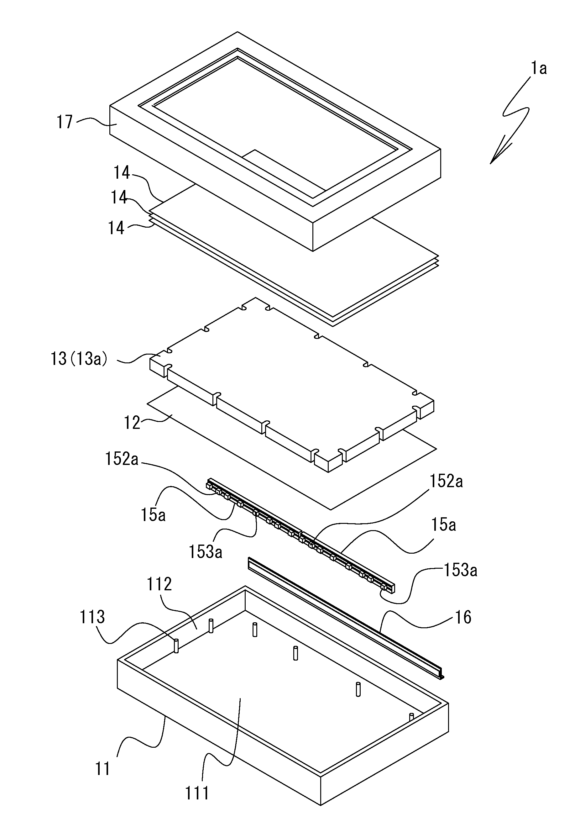
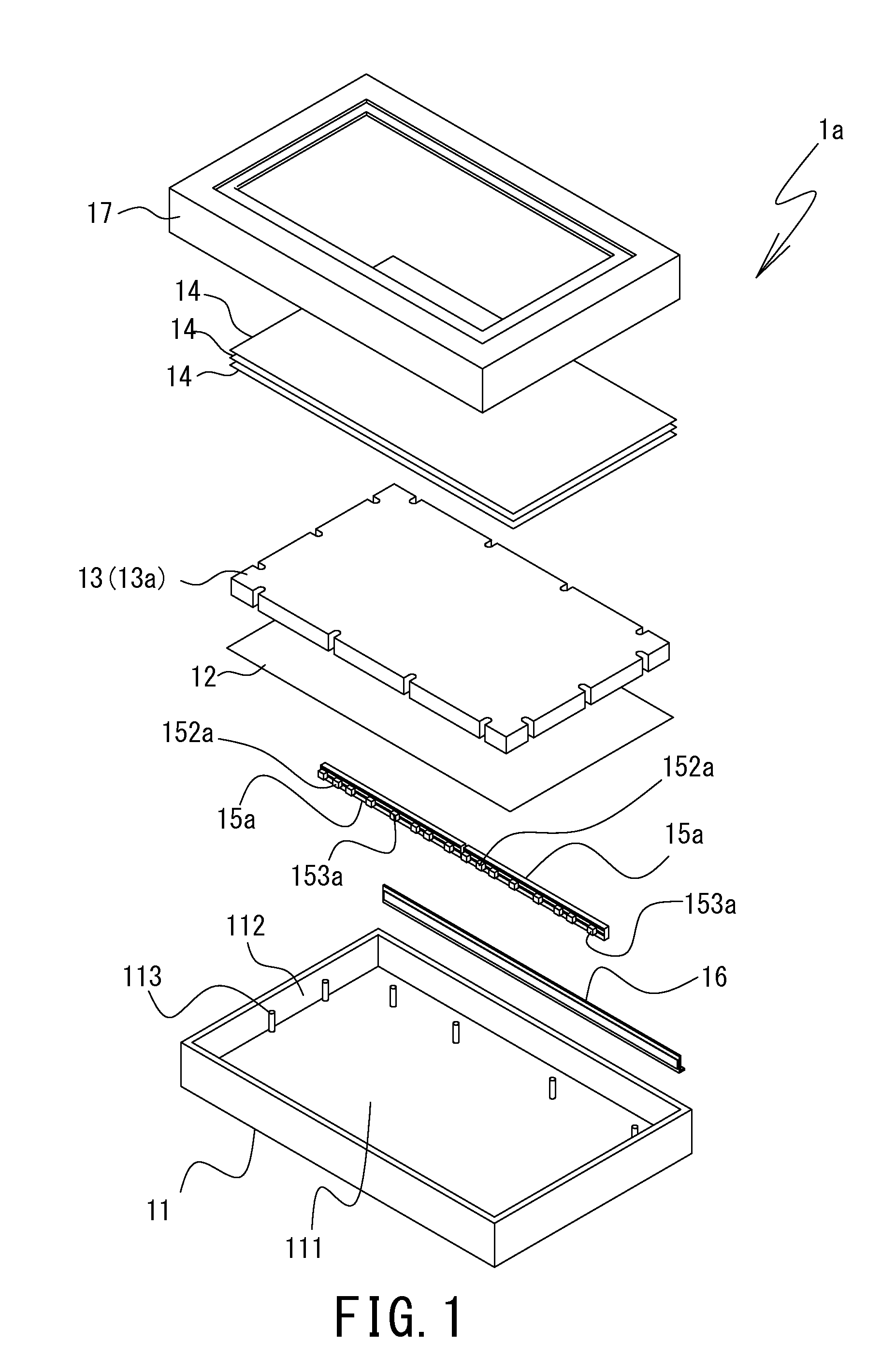
[0043]The chassis 11 defines a housing of the light source device 1a of the The chassis 11 is arranged to house the reflection sheet 12, the light guide plate 13 (13a, 13b), the optical sheets 14, the light sources 15a and the light-source fixing member 16. The chassis 11 has the shape of a dish or tray of low height as shown in FIG. 1. The chassis 11 includes a bottom face 111, and a side wall 112 that surrounds the bottom face 111 and protrudes to the front. The chassis 11 houses the reflection sheet 12, the light guide plate 13 (13a, 13b), the optical sheets 14, the light sources 15a and the light-source fixing member 16 within a region surrounded by the side wall 112 on a front side of the bottom face 111. The chassis 11 is preferably made of a metal plate that is subjected to press working. It is also preferable that the chassis 11 is made of a resin that is subjected to injection molding.

[0044]The chassis 11 includes a plurality of locking pins 113 disposed on the bottom face...

second embodiment

[0104]FIG. 6 is an external perspective view showing a schematic configuration of the light source 15b that is used in the light source device 1b of the The light source 15b includes a substrate 151b, and a plurality of light emitting elements 154b that are disposed on one face of the substrate 151b.

[0105]The substrate 151b has a long and thin linear shape as shown in FIG. 6. The shape and size of the substrate 151b can be made same as the shape and size of the substrate 151a. A wiring pattern and a land (not shown) provided on the substrate 151b may have the same configurations as the wiring pattern and the land of the substrate 151a of the light source 15a of the light source device 1a of the first embodiment, though the light emitting elements 154b are different in kind, number and position. In addition, other constituent elements of the substrate 15b may have the same configurations as the corresponding constituent elements of the substrate 151a of the light source 15a of the ...


PUM


Abstract

Provided is a light source device capable of minimizing or preventing a decrease in amount of light emitted from portions in the vicinity of a locking member of a light guide plate, and capable of making intensity distribution in a plane of light emitted from the light guide plate uniform. The light source device includes a light guide plate 13 (13a, 13b) including a locking member 131a, 131b for disposition and fixing that is disposed on a peripheral portion of the light guide plate or disposed in a vicinity of the peripheral portion, and
    • a light source (15a) capable of projecting light onto the peripheral portion, wherein the light that is projected from the light source onto portions of the light guiding plate, the portions being in the vicinity of the locking member, is higher in intensity than the light projected onto the other portions of the light guiding plate.

Description

TECHNICAL FIELD[0001]The present invention relates to a light source device and a display device, and more specifically relates to a side light source device (referred to also as a side backlight unit or an edge light backlight unit) that is used in a display device, and a display device including the side light source device.BACKGROUND ART[0002]A display device including a transflective or transmissive display panel (e.g., a transflective or transmissive liquid crystal display panel) usually includes a light source device (referred to also as a backlight) disposed behind the display panel. Light emitted from the light source device is projected onto a back face of the display panel, whereby an image is displayed visible on a front face of the display panel.[0003]A side light source device (referred to also as a side backlight unit or an edge light backlight unit) is one example of a light source device used in the display device. A conventionally-used general side light source devi...

Claims


Application Information

Patent Timeline
IPC IPC(8): F21V8/00
CPCG02B6/0068G02B6/0088G02B6/0073
Inventor OYA, TOMOAKI
Owner SHARP KK
Why Eureka
Try Eureka