
Single transmission line for connecting radio frequency modules in an electronic device

a technology of radio frequency modules and transmission lines, applied in the field of radio frequency systems, can solve the problems of increasing the bill of materials (bom) of consumer electronics devices, and the cost of cables is relativity high

Active Publication Date: 2012-12-06
QUALCOMM INC
View PDF6 Cites 47 Cited by
  • Summary
  • Abstract
  • Description
  • Claims
  • Application Information

AI Technical Summary

Benefits of technology

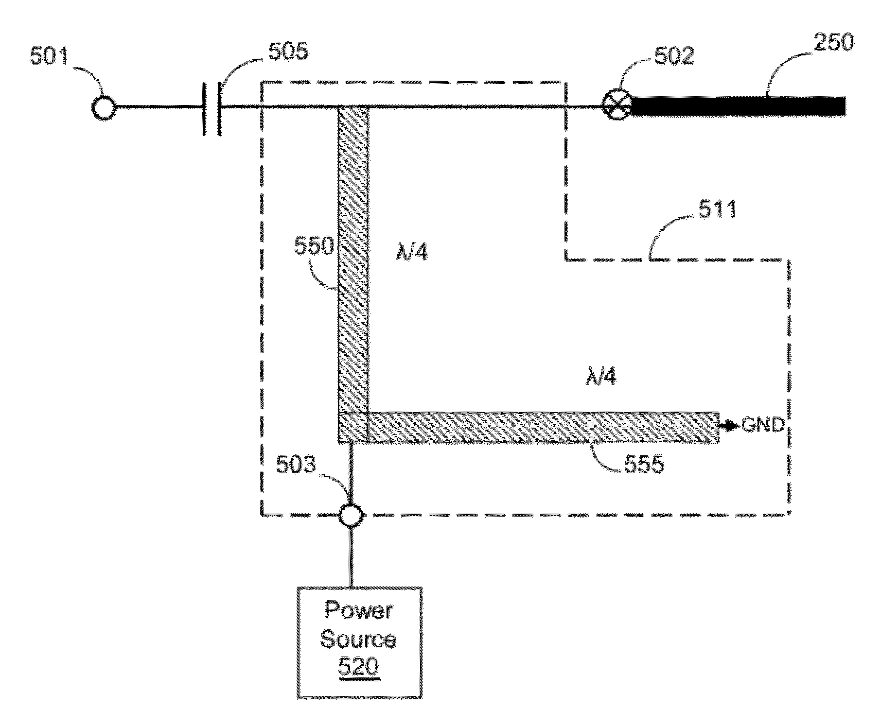
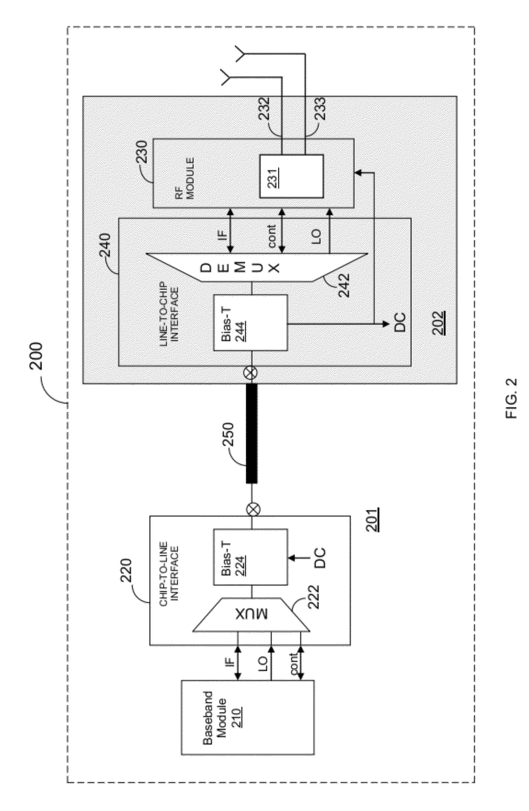
[0012]Certain embodiments disclosed herein include a method for transferring a plurality of signals over a single transmission line connected between modules of a millimeter-wave RF system. The method comprises setting a frequency plan for separating a frequency spectrum to a baseband frequency band, a local oscillator (LO) frequency band, and a control frequency band; at a first module of the RF system performing: multiplexing, using a plurality of frequency filters, baseband signals, a LO signal, and a control signal to produce a first multiplexed signal, wherein the baseband signals, the LO signal, and the control signal are respectively passed at the baseband frequency band, the LO frequency band, and the control frequency band; inserting a power signal to the first multiplexed signal to produce a second multiplexed signal including the baseband signals, the LO signal, the control signal, and the power signal; and transferring the second multiplexed signal to a second module of the RF system over the single transmission line.

Problems solved by technology

However, such cables are relativity expensive, thus increasing the bill of material (BoM) of consumer electronics devices.

Method used


Image

  • Single transmission line for connecting radio frequency modules in an electronic device
  • Single transmission line for connecting radio frequency modules in an electronic device
  • Single transmission line for connecting radio frequency modules in an electronic device

Examples


Embodiment Construction

[0022]The embodiments disclosed by the invention are only examples of the many possible advantageous uses and implementations of the innovative teachings presented herein. In general, statements made in the specification of the present application do not necessarily limit any of the various claimed inventions. Moreover, some statements may apply to some inventive features but not to others. In general, unless otherwise indicated, singular elements may be in plural and vice versa with no loss of generality. In the drawings, like numerals refer to like parts through several views.

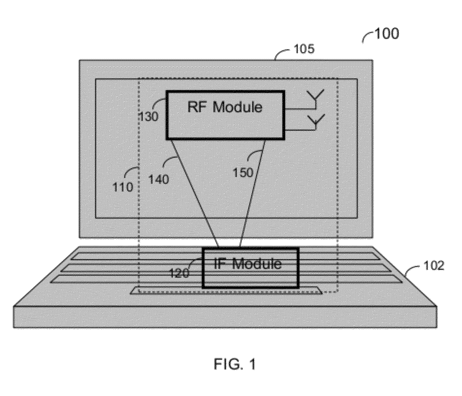
[0023]Certain embodiments disclosed herein enable the connectivity of various RF modules using a single transmission line. In one embodiment, the connectivity is between a baseband module and a RF module, including active electrical elements in an electronic device having a distributed form factor of a motherboard and RF module.

[0024]A schematic diagram of an RF system 200 utilized to describe various embodim...


PUM


Abstract

A millimeter-wave radio frequency (RF) system, and method thereof for transferring multiple signals over a single transmission line connected between modules of a millimeter-wave RF system. The system comprises a single transmission line for connecting a first part of the RF system and a second part of the RF system, the single transmission line transfers a multiplexed signal between the first part and second part, wherein the multiplexed signal includes intermediate frequency (IF) signal, a local oscillator (LO) signal, a control signal, and a power signal; the first part includes a baseband module and a chip-to-line interface module for interfacing between the baseband module and the single transmission line; and the second part includes a RF module and a line-to-chip interface module for interfacing between the RF module and the single transmission line, wherein the first part and the second part are located away from each other.

Description

TECHNICAL FIELD[0001]The present invention generally relates to radio frequency (RF) systems, and more particularly to enabling connectivity, and transmission of signals between RF modules of a RF system using a single transmission line.BACKGROUND OF THE INVENTION[0002]The 60 GHz band is an unlicensed band which features a large amount of bandwidth and a large worldwide overlap. The large bandwidth means that a very high volume of information can be transmitted wirelessly. As a result, multiple applications, that require transmission of a large amount of data, can be developed to allow wireless communication around the 60 GHz band. Examples for such applications include, but are not limited to, wireless high definition TV (HDTV), wireless docking stations, wireless Gigabit Ethernet, and many others.[0003]In order to facilitate such applications there is a need to develop integrated circuits (ICs), such as amplifiers, mixers, radio frequency (RF) analog circuits, and active antennas ...

Claims


Application Information

Patent Timeline
Patent Type & Authority Applications(United States)
IPC IPC(8): H04W4/00
CPCH04B7/24H01P5/20H01P3/06H04L25/026
Inventor YEHEZKELY, ALONSASSON, ORI
Owner QUALCOMM INC
Learn More