Supercharge Your Innovation With Domain-Expert AI Agents!

Distributed antenna system

a distributed antenna and antenna technology, applied in the direction of orthogonal multiplex, multiplex communication, frequency-division multiplex, etc., can solve the problems of wasting existing equipment, difficult to carry out communication through carrier aggregation in the conventional distributed antenna system,

Inactive Publication Date: 2012-12-06
HITACHI METALS LTD
View PDF1 Cites 15 Cited by
  • Summary
  • Abstract
  • Description
  • Claims
  • Application Information

AI Technical Summary

Benefits of technology

[0016]Accordingly, it is an object of the invention to provide a distributed antenna system that can be used to perform a communication between an antenna and a mobile terminal by means of the carrier aggregation using a low-frequency band and a high-frequency band only by making a small modification to the existing equipments.
[0017]a first antenna disposed covering a predetermined communication range, the first antenna carrying out a communication at least at a low-frequency band; and
[0018]a plurality of second antennas disposed covering the predetermined communication range, the plurality of second antennas carrying out a communication at a high-frequency band,
[0019]wherein the distributed antenna system is operable to carry out a communication between the first antenna and the second antennas, and a mobile terminal located within the predetermined communication range by means of carrier aggregation using the low-frequency band and the high-frequency band, and

Problems solved by technology

In order to carry out a communication by means of the carrier aggregation, it is needed to handle plural frequency bands at the same time, however, each antenna is connected to BB module of different base station respectively, thereby collaboration between the base stations is not achieved, thus it is difficult to carry out the communication by means of the carrier aggregation in the conventional distributed antenna system.
For adapting to the carrier aggregation, one may consider developing a new distributed antenna system adapted hereto, but this consideration allows the waste of the existing equipments.

Method used


Image

  • Distributed antenna system
  • Distributed antenna system
  • Distributed antenna system

Examples


Embodiment Construction

[0038]The preferred embodiments according to the invention will be explained below referring to the drawings.

[0039]First, the carrier aggregation will be explained.

[0040]The carrier aggregation includes a method that carriers of continuous frequency bands A, B and C are used at the same time as shown in FIG. 5A and a method that carriers of discontinuous frequency bands A, B and C are used at the same time as shown in FIG. 5B.

[0041]It is an object of any of the above-mentioned methods to pursue an enhancement of throughput by securing band frequencies across plural frequency bands and using them at the same time. In the carrier aggregation, frequency bands are secured across plural frequency bands, thus collaboration of signal processing between frequency bands is essential.

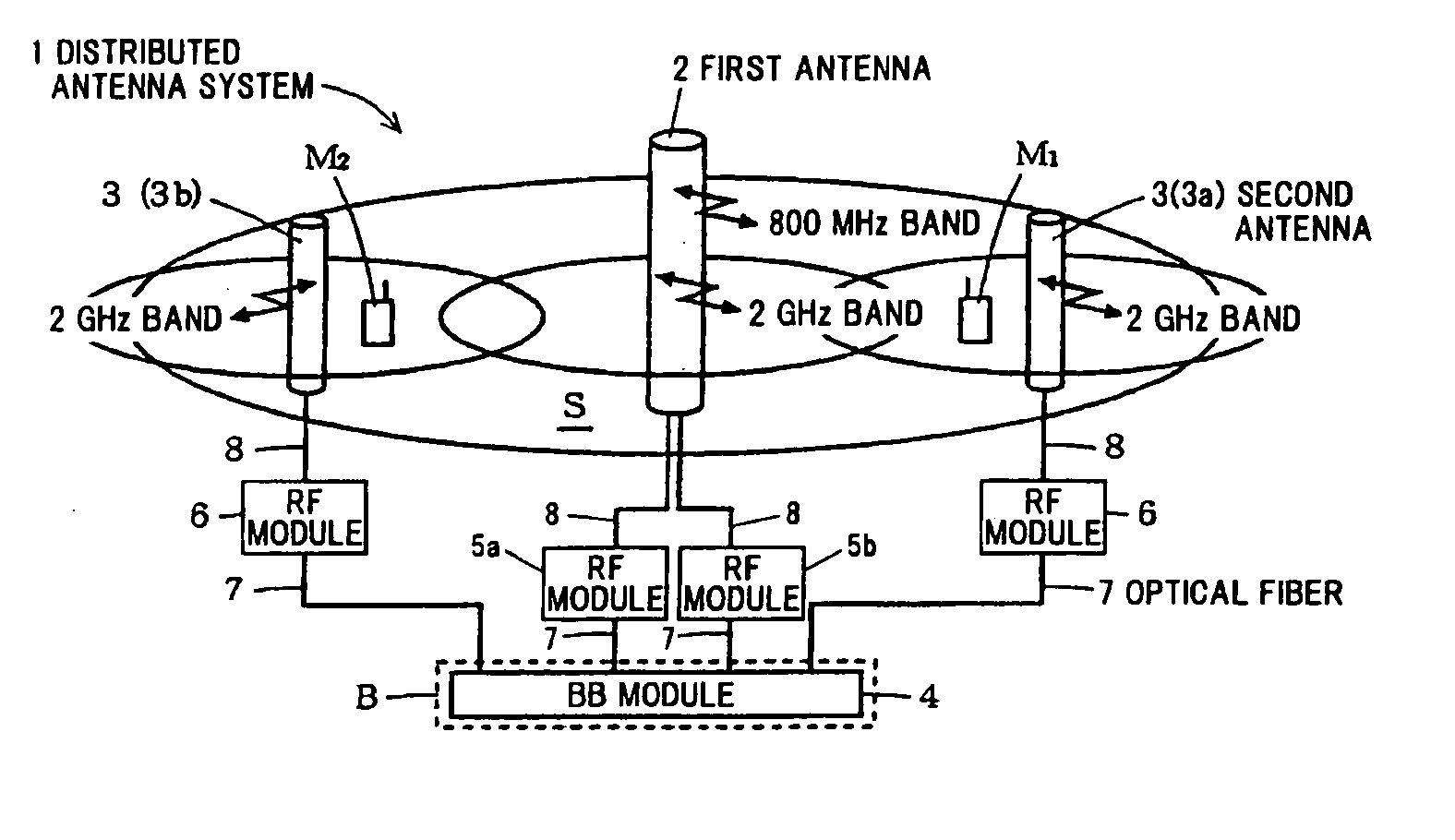
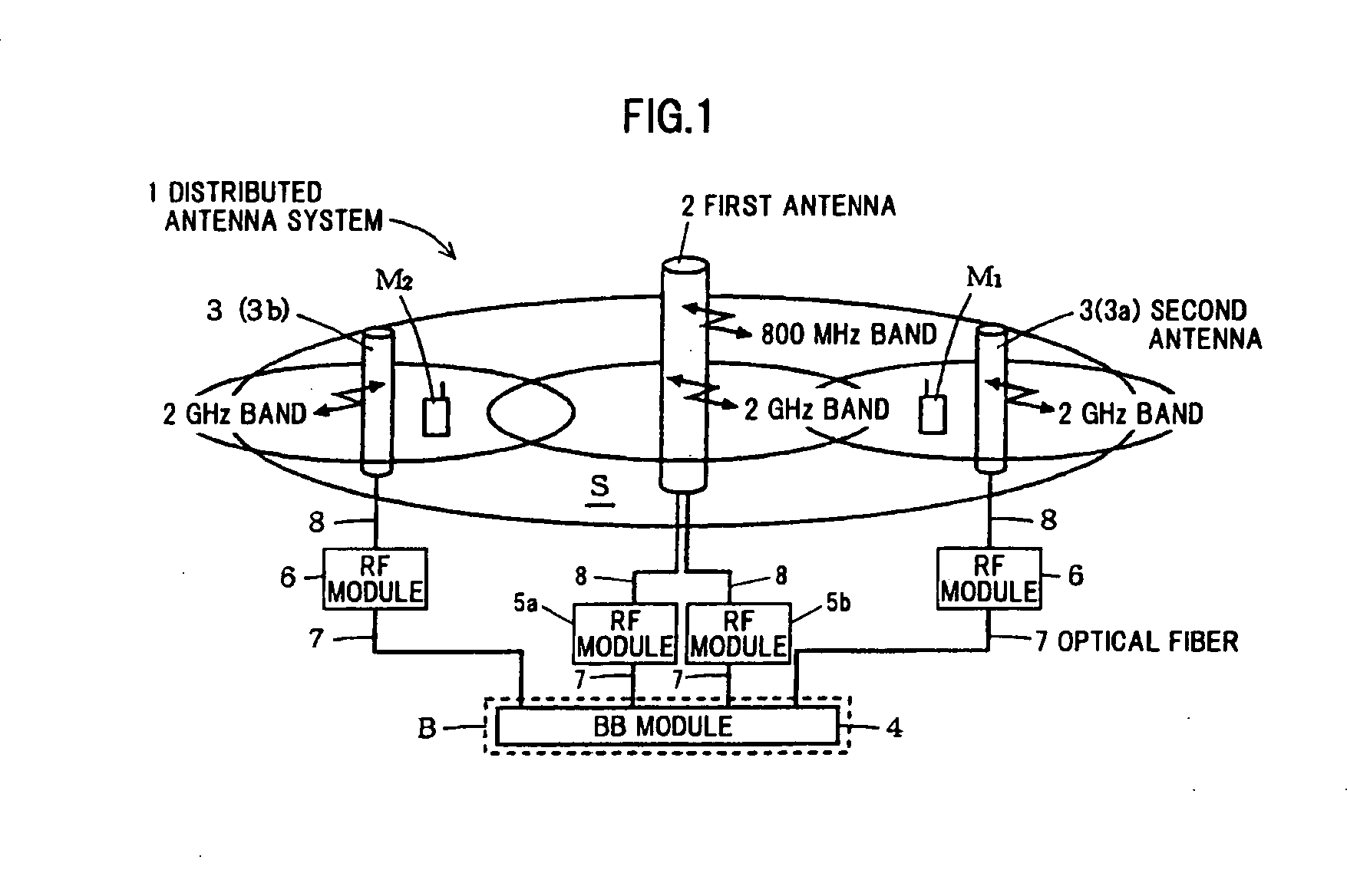
[0042]However, the current distributed antenna system has only a configuration that plural antennas for high-frequency band are disposed in a base station installed in each place so as to cover a communication ra...


PUM


Abstract

A distributed antenna system includes a first antenna disposed covering a predetermined communication range, the first antenna carrying out a communication at least at a low-frequency band, and a plurality of second antennas disposed covering the predetermined communication range, the plurality of second antennas carrying out a communication at a high-frequency band. The distributed antenna system is operable to carry out a communication between the first antenna and the second antennas, and a mobile terminal located within the predetermined communication range by means of carrier aggregation using the low-frequency band and the high-frequency band. The distributed antenna system further includes a BB module equipped in a base station for carrying out a communication within the predetermined communication range, the first antenna and the second antennas being each connected to the one BB module via an RF module.

Description

[0001]The present application is based on Japanese patent application Nos. 2010-128629 and 2011-124780 filed on Jun. 4, 2010 and Jun. 3, 2011, respectively, the entire contents of which are incorporated herein by reference.BACKGROUND OF THE INVENTION[0002]1. Field of the Invention[0003]This invention relates to a distributed antenna system for carrying out a communication between an antenna and a mobile terminal by means of carrier aggregation using a low-frequency band and a high-frequency band.[0004]2. Description of the Related Art[0005]In a mobile communication system, there are a base station and a mobile terminal that use plural frequency bands such as 800 MHz band and 2 GHz band.[0006]As shown in FIG. 4, in the base station using the plural frequency bands, a wireless system 21a for the 800 MHz band and a wireless system 21b for the 2 GHz band are connected to a single antenna 20. The wireless systems 21a, 21b are respectively equipped with RF modules 22a, 22b and BB modules ...

Claims


Application Information

Patent Timeline
Patent Type & Authority Applications(United States)
IPC IPC(8): H04B10/10H04B7/00H04B1/3822H04B1/40H04J1/00H04J11/00H04J99/00H04W88/08
CPCH04B1/40H04L5/001H04L5/0023
Inventor SHIDA, MASAAKI
Owner HITACHI METALS LTD
Features
  • R&D
  • Intellectual Property
  • Life Sciences
  • Materials
  • Tech Scout
  • Unparalleled Data Quality
  • Higher Quality Content
  • 60% Fewer Hallucinations
Learn More