Coalescing filter

a filter and coalescing technology, applied in the direction of filtration separation, machine/engine, separation process, etc., can solve the problem that water is not readily re-dissolved in fuel, and achieve the effect of significantly reducing or removing the maintenance of the water drain system

Inactive Publication Date: 2012-12-13
AIRBUS OPERATIONS LTD
View PDF4 Cites 27 Cited by
  • Summary
  • Abstract
  • Description
  • Claims
  • Application Information

AI Technical Summary

Benefits of technology

[0021]To equalise pressures in the fuel system, a vent system may be used. When there is a net inflow of ambient air into the fuel system, water vapour may condense out onto cool surfaces. This water condensate would typically require water drain maintenance. In a preferred embodiment, the fuel system may further comprise a vent system for ventilating the fuel tank, wherein a water drain

Problems solved by technology

Once condensation occurs and water droplets have coalesced into larger droplets, pools and films, water is not rea

Method used


Image

  • Coalescing filter
  • Coalescing filter
  • Coalescing filter

Examples


first embodiment

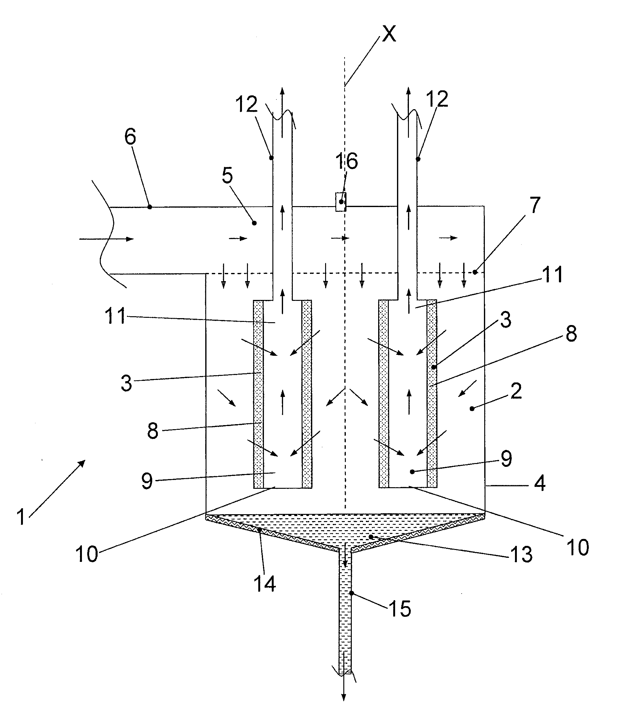
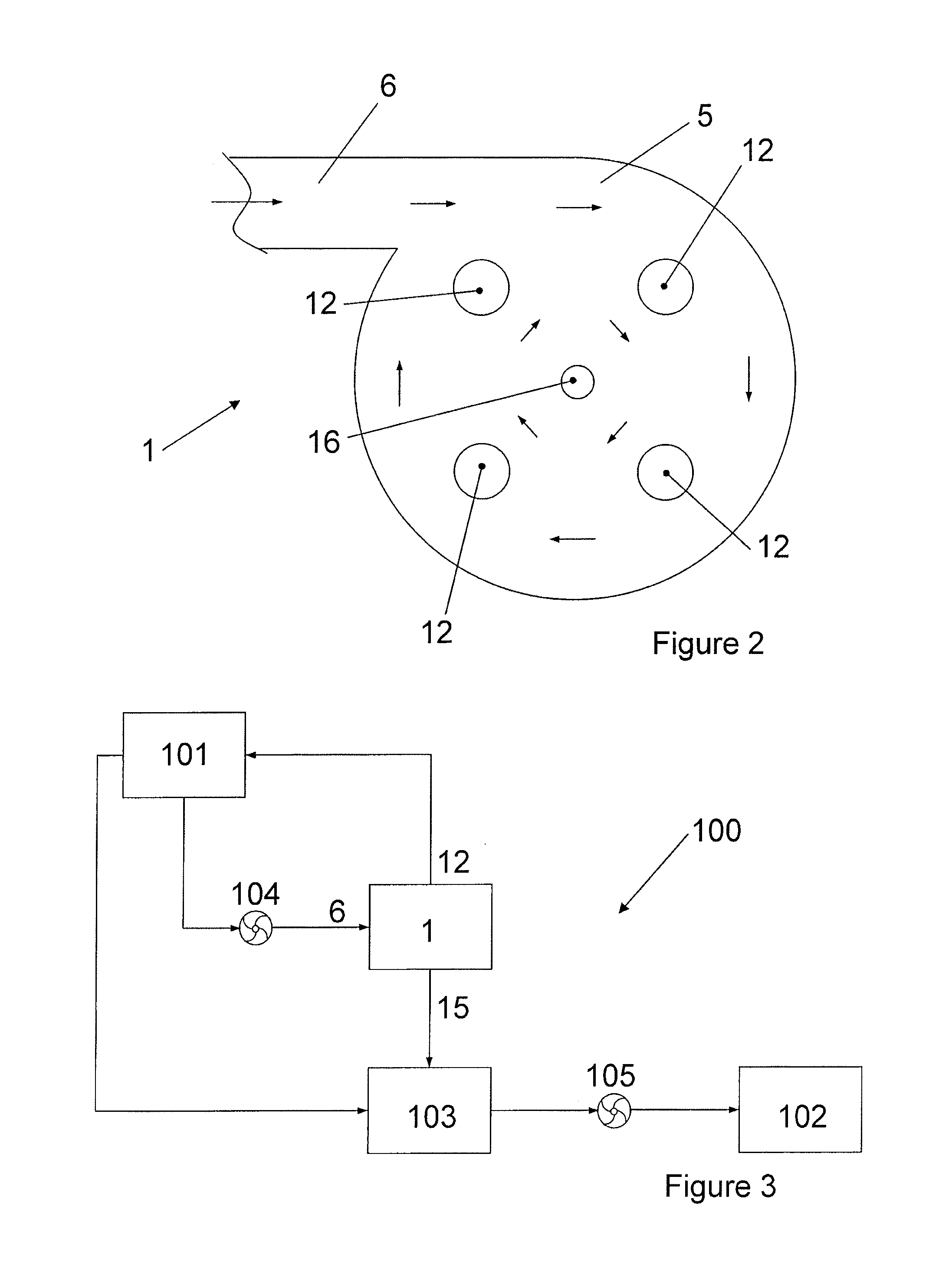
[0037]Water rich filtrand is drained off from the sump 13 through the first outlet 15 to the engine feed inlet 103 of an engine feed system. The engine feed system mixes the water rich filtrand with fuel from the tank 101 such that the concentration of water entrained into the fuel fed to the engine 102 by engine feed pump 105 is within acceptable limits set by the engine manufacturer. The filter 1 is adapted to perform a self purging operation for the filter cartridges 3. In this first embodiment, the filter 1 includes a manifold valve arrangement for reversing the direction of flow of the fuel filtrate through each of the filter cartridges 3 in turn during the purging operation. The manifold valve arrangement and the purging operation will now be described in detail with reference to FIG. 4.

[0038]FIG. 4 illustrates the manifold valve arrangement 17 for the filter 1. The manifold valve arrangement 17 includes a forward flow manifold 18, a return flow manifold 19, a pump 20 and a di...

second embodiment

[0044]FIG. 5 illustrates the filter 11 which shares many features in common with the filter 1 described above with reference to FIGS. 1 and 2. As such, like reference numerals have been used in FIG. 5 to denote like parts in FIG. 1 and only the differences between the filter 11 and the filter 1 will now be described.

[0045]The filter 11 includes a water drain outlet 22 which opens into an induction chamber 23 at the filter inlet 6. The water drain outlet 22 is connected to a water scavenge system and / or a water drain of a vent system. Water which condenses out of the fuel in the fuel tank 101 tends to run down the tank walls and collect, or pool in one or more low points of the fuel tank. The water scavenge system includes an inlet at these low points and the water scavenge system draws the pooled water through the inlet. The motive flow of fuel entering the filter inlet 6 induces a flow through the water scavenge system such that the scavenged water exits the water drain outlet 22 a...


PUM

PropertyMeasurementUnit
Flow rateaaaaaaaaaa

Abstract

A fuel system comprising a liquid fuel tank, an engine, and a coalescing filter adapted to separate water from fuel, the filter having an inlet fluidically connected to the fuel tank, a first outlet fluidically connected to a fuel feed system for the engine, and a second outlet fluidically connected to the fuel tank, wherein the coalescing filter is adapted to discharge fuel filtrate from the second outlet and filtrand from the first outlet. Also, a method of removing water or ice from a fuel tank, the method comprising directing a flow of fuel from a fuel tank to a coalescing filter adapted to separate water from fuel, discharging filtrand from a first outlet of the coalescing filter to a fuel feed system for consumption by an engine, and discharging fuel filtrate from a second outlet of the coalescing filter and returning the fuel filtrate to the fuel tank.

Description

FIELD OF THE INVENTION[0001]The present invention relates to a fuel system including a coalescing filter for separating water from fuel. Also, a method of removing water or ice from a fuel tank.BACKGROUND OF THE INVENTION[0002]Water is an unavoidable contaminant in fuel. Water can affect components in fuel systems and lead to operational delays and increased maintenance activities. In addition, the propensity for microbiological contamination is directly proportional to the presence of water and the temperature within fuel tanks.[0003]Although water may affect fuel systems of land or water based vehicles, water is a particular problem in aircraft fuel systems. Water may enter aircraft fuel tanks from fuel loaded into the aircraft fuel tanks during refuel (dissolved water) and from air entering the aircraft fuel tanks via its vent system. A vent system to ambient air is normally required to normalise the pressure within the fuel tanks during climb and descent of the aircraft.[0004]Si...

Claims


Application Information

Patent Timeline
IPC IPC(8): F02M37/00F02C7/22B01D37/00F02M37/24F02M37/30F02M37/50F02M37/54
CPCF02M37/0052F02M37/223F02M37/221F02M37/30F02M37/24F02M37/54F02M37/50
Inventor LAM, JOSEPH K-WTICHBORNE, FRANKLINPARMENTER, DAVIDMASTERS, SIMON
Owner AIRBUS OPERATIONS LTD
Why Eureka
Try Eureka