Point source assembly for thin film deposition devices and thin film deposition devices employing the same

Inactive Publication Date: 2012-12-13
HELIOVOLT CORP
View PDF3 Cites 4 Cited by
  • Summary
  • Abstract
  • Description
  • Claims
  • Application Information

AI Technical Summary

Benefits of technology

[0017]The present invention relates generally to a point source assembly for a thin film deposition device having a chamber for holding a substrate in which the longitudinal axis of the opening leading to the chamber and the longitudinal axis of the point source can vary from one another in situ thus providing a more convenient, real-time means for making deposition adjustments.
[0018]The point source assembly of the present invention generally includes a crucible for holding and vaporizing a deposition material to generate a vapor flux plume and an opening in the crucible for directing the vapor flux plume containing the vaporized deposition material toward a substrate. The vapor flux plume travels to the substrate and condenses on the surface of the substrate to form a thin film thereon. The point source assembly of the present invention is designed to enable the characteristics of the vapor flux plume to be readily changed or modified by enabling the longitudinal axis of the opening leading to the chamber and the longitudinal axis of the point source assembly to vary with respect to each other in situ. In this manner, the uniformity of resulting thin film deposition can be tailored as desired. The present invention improves production yield, while reducing the time and labor typically associated with thin film deposition of substrates.

Problems solved by technology

Post deposition operations add significantly to the cost and time of producing finished substrates.
This approach is very costly, time consuming, and labor-intensive.

Method used


Image

  • Point source assembly for thin film deposition devices and thin film deposition devices employing the same
  • Point source assembly for thin film deposition devices and thin film deposition devices employing the same
  • Point source assembly for thin film deposition devices and thin film deposition devices employing the same

Examples


Embodiment Construction

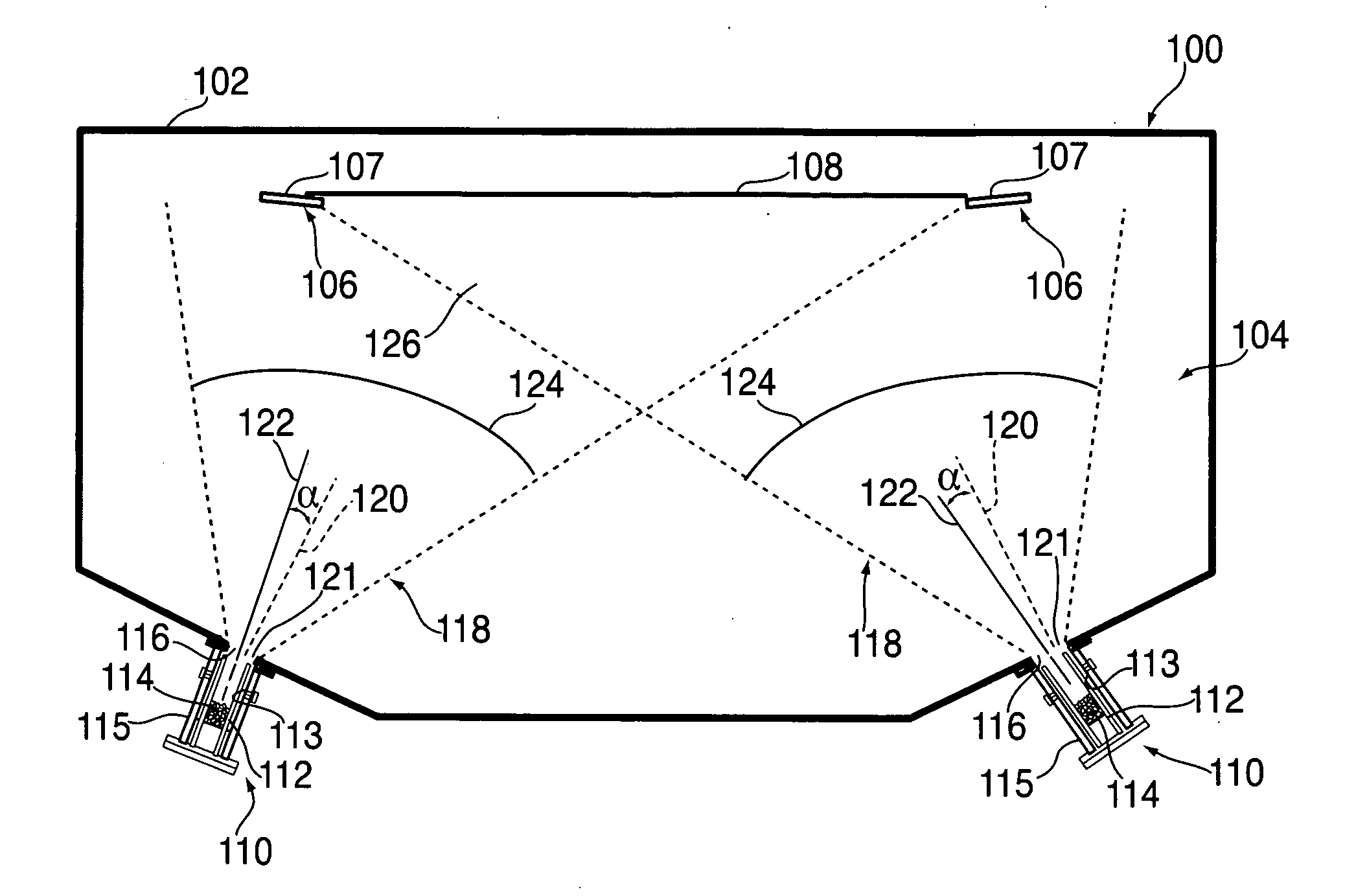
[0035]The present invention is generally directed to a point source assembly for a thin film deposition device having a chamber for holding a substrate in which the orientation of the longitudinal axis of the opening leading to the chamber and the longitudinal axis of the point source is varied from one another during the deposition process.

[0036]The point source assembly of the present invention generally includes a crucible for holding and vaporizing a deposition material to generate a vapor flux plume which passes through an opening in the crucible and is thereby directed toward a substrate through a corresponding opening in the chamber. The vapor flux plume travels to the substrate and condenses on the surface of the substrate to form a thin film thereon. The point source assembly of the present invention is designed to enable the characteristics of the vapor flux plume to be readily changed or modified in situ. In this manner, the uniformity of resulting thin film deposition ca...


PUM

PropertyMeasurementUnit
Angleaaaaaaaaaa
Angleaaaaaaaaaa
Angleaaaaaaaaaa

Abstract

A point source assembly for a thin film deposition device having a chamber for holding a substrate, includes a crucible configured for holding and vaporizing a deposition material therein, where the crucible is configured for operative engagement to the chamber, an opening in the crucible configured for directing therefrom a vaporized form of the deposition material, where the opening includes a longitudinal line extending through the center of the crucible opening, and means operatively engaged to the crucible for facilitating rotational movement of the crucible for varying the orientation of the longitudinal line relative to the position of the substrate in the chamber.

Description

FIELD OF THE INVENTION[0001]The present invention relates to thin film deposition, and more particularly a point source assembly for a thin film deposition device, and thin film deposition devices employing the same for depositing thin films.BACKGROUND OF THE INVENTION[0002]Several methods for depositing thin films on substrates (i.e., deposition targets) are known in the art. Such methods include physical vapor deposition and chemical vapor deposition. One common form of thin film deposition is evaporation deposition. Evaporation deposition involves vaporizing a deposition or source material under high vacuum, and condensing the vaporized deposition material on a substrate to form a thin film. Operating under vacuum conditions allows the vaporized deposition material to travel unhindered in a direct path to the substrate where it condenses back to a solid state. This process is used to produce thin films with a relatively high level of purity desirable in many applications. The dep...

Claims


Application Information

Patent Timeline
IPC IPC(8): C23C16/448
CPCC23C14/243
Inventor LOBUE, JOSEPH D.
Owner HELIOVOLT CORP
Why Eureka
Try Eureka