[0009]In the context of a mould for forming a composite, the matrix material is the substance used to bond and support the reinforcement
layers. In the prior art moulding techniques, as described above, the matrix material will also bond to the mould unless a release agent is used. An obvious
advantage of the mould according to the invention is that the
solid non-stick lining makes a release agent unnecessary and, after curing, the wind turbine blade can easily be detached from the non-stick lining. Therefore, savings can be made as regards to time and cost, since no time need be spent with the exacting application of a release agent layer, and as regards to health, since workers need not be exposed to any
solvent fumes. Furthermore, the surface of the blade, after curing and removal from the mould, is free of any problematic remnants of release agent and is essentially ready for a final finishing step such as painting. Also, the solid non-stick lining favourably inhibits air-pockets from being trapped at the outer surface of the component, so that pinholes are essentially prevented from developing. These positive aspects can save considerable time and expense while allowing the manufacture of a blade with a high-quality outer surface.
[0013]The term ‘solid’ in the context of the non-stick lining is used in the sense that the non-stick lining is not a
wax or other semi-
solid material, in order to distinguish it completely from any release agent that is manually applied to coat the inside of a mould in a prior art technique. In a particularly preferred embodiment of the invention, the solid non-stick lining comprises a layer of a polytetrafluoro-
ethylene (PTFE) material, such as Teflon®, which is a
registered trademark of the DuPont company. The solid non-stick lining can be applied just once to the inside surface of the mould, which can then be used multiple times without having to replace the non-stick lining.
[0016]In one approach, the composite lay-up can comprise layers of prepreg material, in which the reinforcing material layers are already soaked or impregnated with matrix material such as a
thermosetting polymer or any suitable
epoxy resin. To cure the layers, heat can be applied to the mould. To this end, the mould preferably comprises a
heating element, for example a heating filament or coil embedded in the mould body. Prior to curing, air is usually drawn out of the closed mould so that the material layers expand to fill the mould and to press against the inside surface of the mould, thus ensuring a smooth outer surface of the finished component. To this end, the closed mould preferably comprises airtight seals to facilitate the development of a satisfactory vacuum.
[0019]When laying-up the
composite material layers in the mould,
cutting tools may be used to
cut the layers to size. As a result, it may happen that the non-stick lining is damaged in places. In any areas from which the non-stick lining is nicked or chipped out, the matrix material would bond to the inside surface of the mould, leading to difficulties when removing the cured blade and possibly damaging the blade outer surface or the mould. Therefore, the step of applying the solid non-stick lining to the inside surface of the mould can comprise applying a piece or strip of non-stick lining to cover a defect in the non-stick lining (already applied to the mould) as required. For example, a thin strip of self-
adhesive Teflon tape could be stuck onto the damaged region. Preferably, the strip can be
cut to size to optimally cover the defect with little overlap. In this way, the non-stick lining can be repaired in a cost-effective and quick manner, by using just small pieces of tape to repair defects as they arise. Effectively, by being able to repair defects in this way, the solid non-stick lining can be re-used indefinitely.
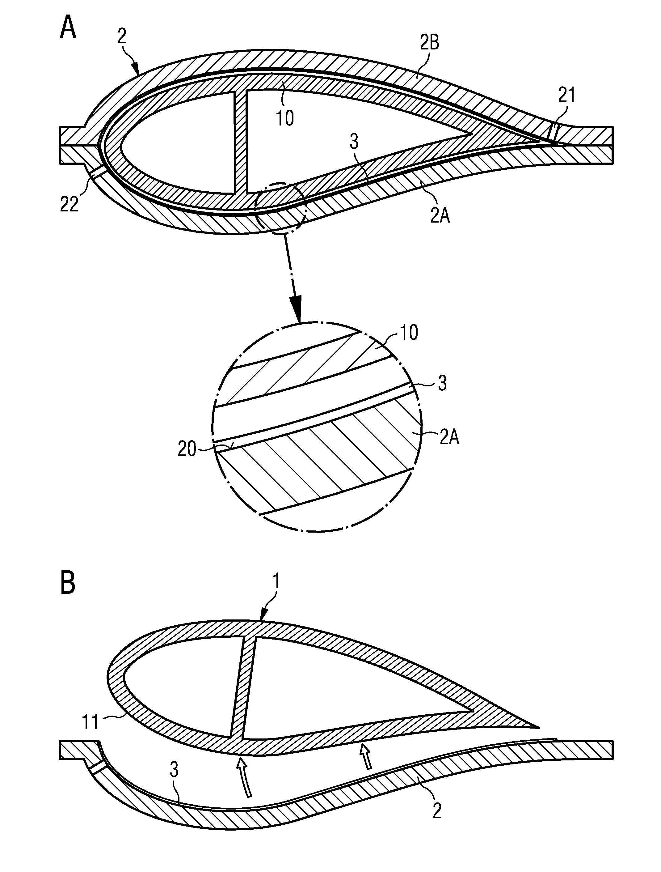
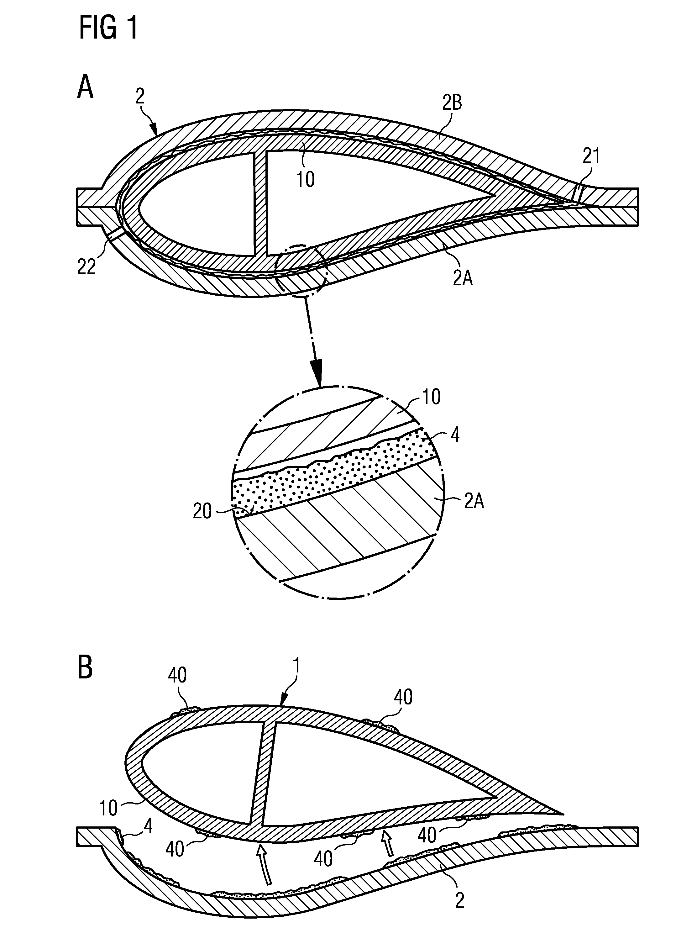
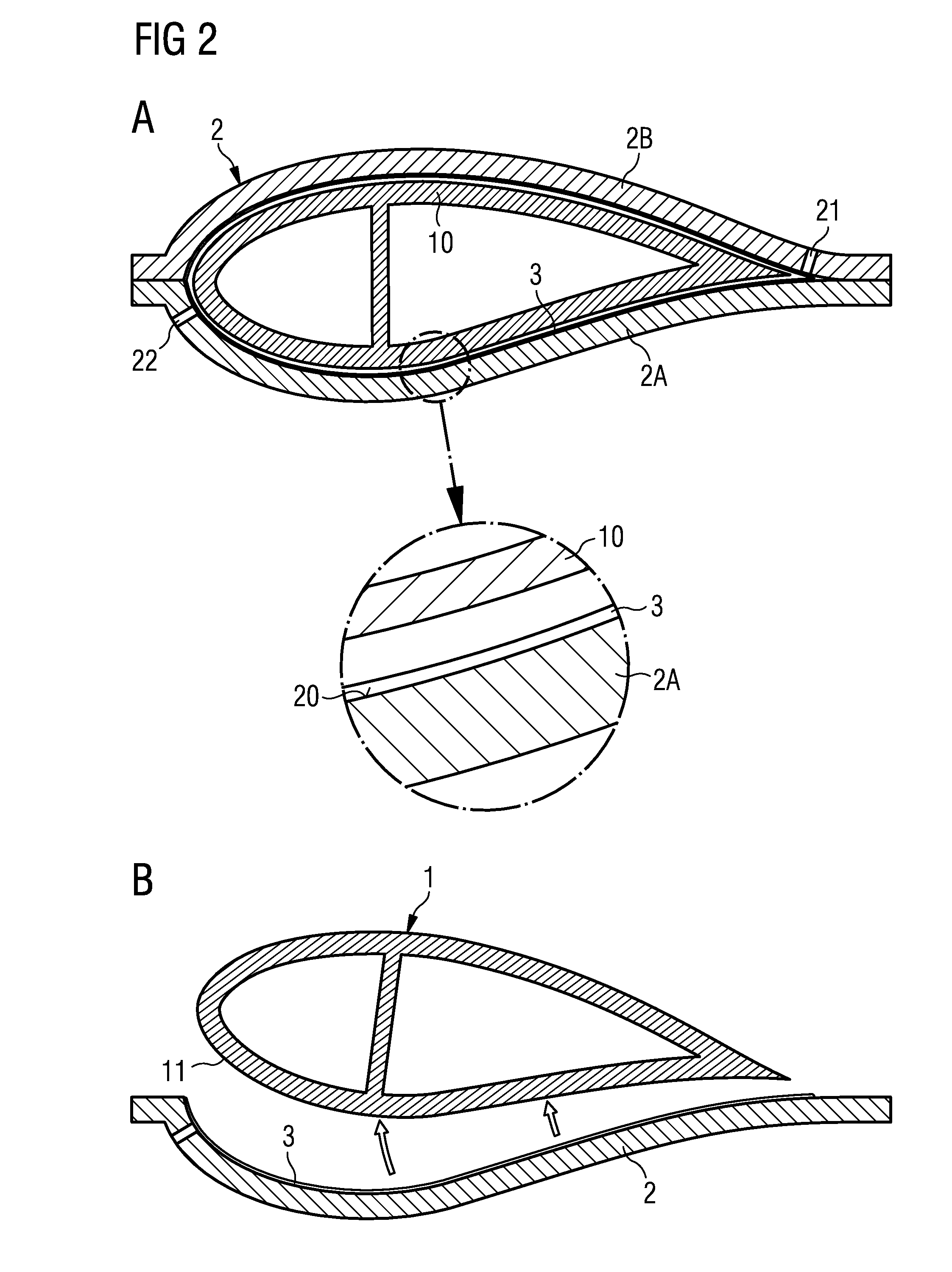
[0020]However, depending on the reinforcing materials and the matrix materials used, it may be desirable to have some means of collecting any excess matrix material. Therefore, in a further embodiment of the invention, the method comprises an additional step of laying out an additional—disposable—layer of composite fabric on top of the solid non-stick lining prior to laying up the component layers. An example of such a composite fabric is Compoflex® (a product of the Fibertex company), which is made of several different functional layers. For example, a Compoflex® fabric comprising a bleeder layer and a
breather layer can be used. The bleeder layer is designed to effectively absorb any excess resin that is exuded at the outer surfaces of the component, and the
breather layer helps prevent air pockets being trapped near the component surface. After curing, this additional composite layer can be peeled off the hardened component and discarded.

