Vehicle comfort system with efficient coordination of complementary thermal units

a technology of complementary thermal units and vehicle comfort, which is applied in the field of vehicle comfort systems with efficient coordination of complementary thermal units, can solve the problems of increasing the energy consumption of vehicles to obtain a comfortable climate, the control of supplemental devices has not been integrated with the main hvac system, and the inability to manually set devices, etc., to achieve the greatest comfort benefit, the effect of increasing the relative proportion of energy and achieving the highest energy efficiency

Active Publication Date: 2012-12-13
FORD GLOBAL TECH LLC
View PDF11 Cites 69 Cited by
  • Summary
  • Abstract
  • Description
  • Claims
  • Application Information

AI Technical Summary

Benefits of technology

[0009]Under conditions when thermal demand is highest (i.e., the actual temperature to which the occupant is exposed is farthest from the desired, target temperature), it has been discovered that directing a higher relative proportion of energy into touchpoint thermal devices achieves the greatest comfort benefit at the highest energy efficiency (especially when providing warmth in a cold vehicle). Coordination between the main forced-air components and the touchpoint devices across all conditions greatly reduces energy use while maintaining occupant comfort. T...

Problems solved by technology

Even when included as standard equipment, control of supplemental devices has not been integrated with the main HVAC system.
Besides causing undesirable distraction, it is unlikely that the devices can all be manually set such that the most effective operation is obtained.
Energy usage in the vehicle to obtain a comfortable climate is becoming an important issue.
As one consequence of c...

Method used


Image

  • Vehicle comfort system with efficient coordination of complementary thermal units
  • Vehicle comfort system with efficient coordination of complementary thermal units
  • Vehicle comfort system with efficient coordination of complementary thermal units

Examples


Embodiment Construction

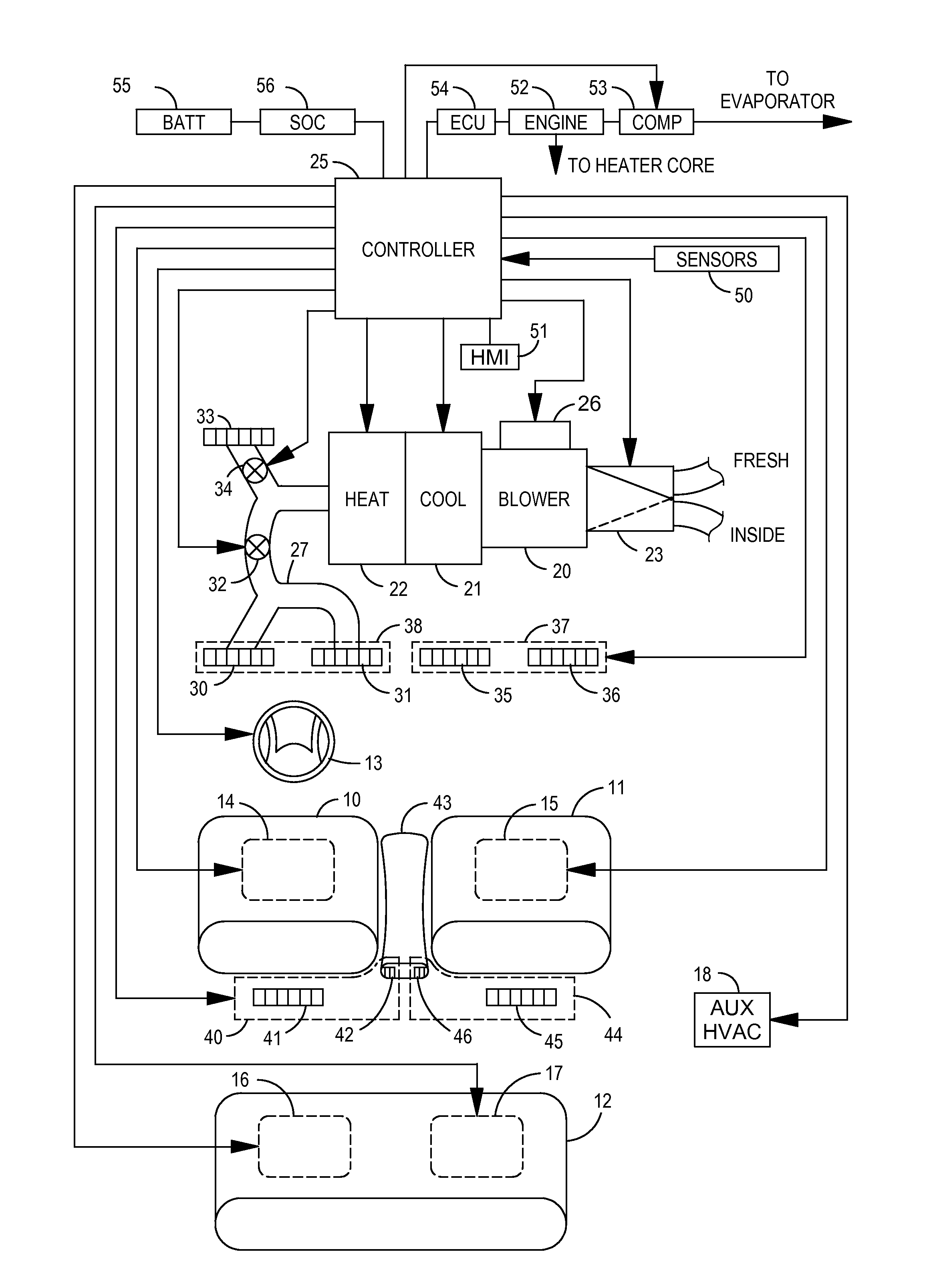
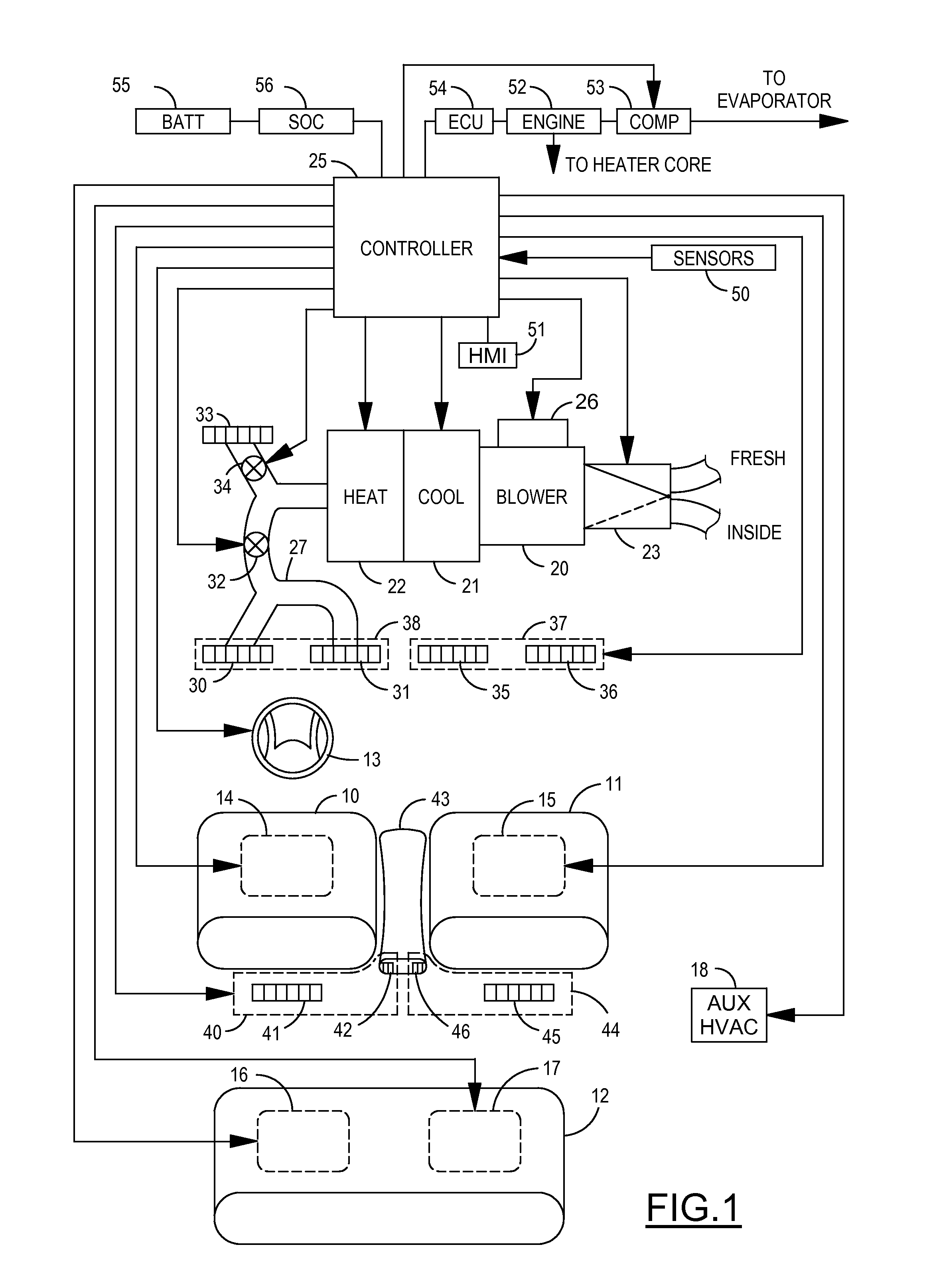
[0015]Referring now to FIG. 1, an automotive vehicle includes a driver seat 10, a passenger seat 11, and a rear seat 12 (which may be a bench seat, rear bucket seats, is or a third row seat). A steering wheel 13 located in front of driver seat 10 includes an internal heat source on the surfaces contacted by the driver's hands (i.e., a touchpoint surface). A known manner of heating steering wheel 31 may be used such as electrical resistance heating based on a positive temperature coefficient (PTC) material built into the steering wheel.

[0016]Additional touchpoint surfaces are preferably included in seats 10-12 to conduct heat to or from the occupants. Specifically, seat thermal units 15-17 can provide heating and / or cooling using known methods such as integral resistive heating elements, integrated chillers, or thermoelectric devices. In addition, an auxiliary HVAC 18 could alternatively be used to heat or cool one or more touchpoint surfaces.

[0017]The vehicle includes a forced-air H...


PUM


Abstract

An HVAC comfort system operates in a cabin of a vehicle. A plurality of vehicle status parameters are measured including a cabin temperature and a seat occupancy configuration. The method detects whether the vehicle status parameters correspond to a predetermined override state. When the vehicle status parameters correspond to the predetermined override state, then a respective mandated setting is automatically activated. Unless prevented by the mandated setting, one of a plurality of HVAC modes is automatically selected in response to the cabin temperature and other inputs, wherein the HVAC modes include an extremity heating mode and a panel circulation mode. The extremity heating mode is comprised of automatic activation of a touchpoint heated surface and other outputs in response to the seat occupancy configuration. The panel circulation mode is comprised of automatic activation of one or more zones for convective cooling in response to the seat occupancy configuration and may include activating other cooling devices.

Description

CROSS REFERENCE TO RELATED APPLICATIONS[0001]Not Applicable.STATEMENT REGARDING FEDERALLY SPONSORED RESEARCH[0002]Not Applicable.BACKGROUND OF THE INVENTION[0003]The present invention relates in general to automotive heating, ventilating, and air conditioning (HVAC) systems, and, more specifically, to a system and method for coordinating multiple heating and cooling devices to provide thermal comfort to vehicle occupants in a manner that optimizes energy expenditure.[0004]Thermal comfort has been provided in conventional automotive vehicles using a forced-air central HVAC system. Supplemental devices such as heated seats, cooled seats, heated steering wheels, or partitioned climate zones have become available for increasing comfort.[0005]Even when included as standard equipment, control of supplemental devices has not been integrated with the main HVAC system. Thus, the user must manually attend to each standalone device in an attempt to balance the overall comfort provided by all t...

Claims


Application Information

Patent Timeline
IPC IPC(8): B60H1/00B60N2/56
CPCB60H1/00285B60H1/00292B60H1/00742B60N2/002B60H1/00835B60H1/00849B60N2/5628B60H1/00785B60H1/00764B60N2/56
Inventor HOKE, PAUL B.LINE, JOHNATHAN A.DAGE, GARY A.SAWYER, ROBERT S.
Owner FORD GLOBAL TECH LLC
Why Eureka
Try Eureka