Optical encoder including displacement sensing normal to the encoder scale grating surface
a technology of displacement sensing and encoder, applied in the direction of optical conversion of sensor output, instruments, measurement devices, etc., can solve the problem of complex structure of the encoder
- Summary
- Abstract
- Description
- Claims
- Application Information
AI Technical Summary
Benefits of technology
Problems solved by technology
Method used
Image

Examples
first embodiment
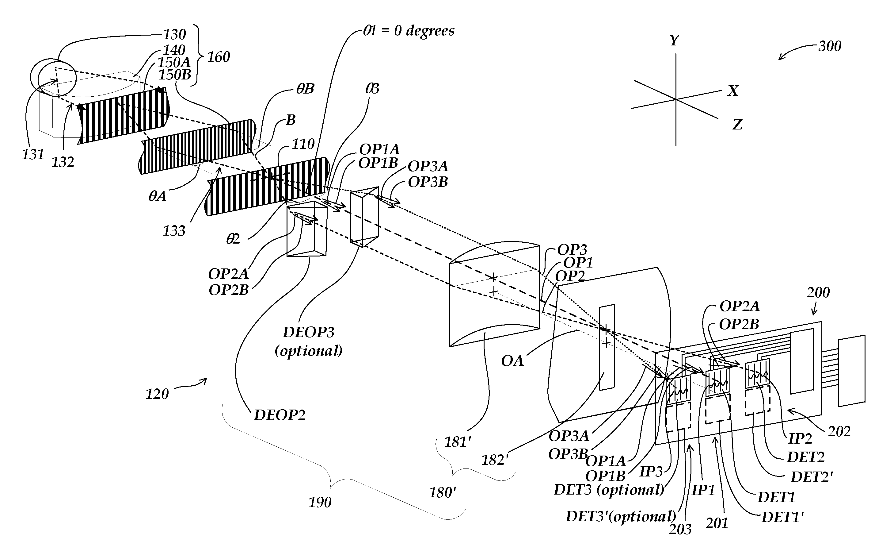
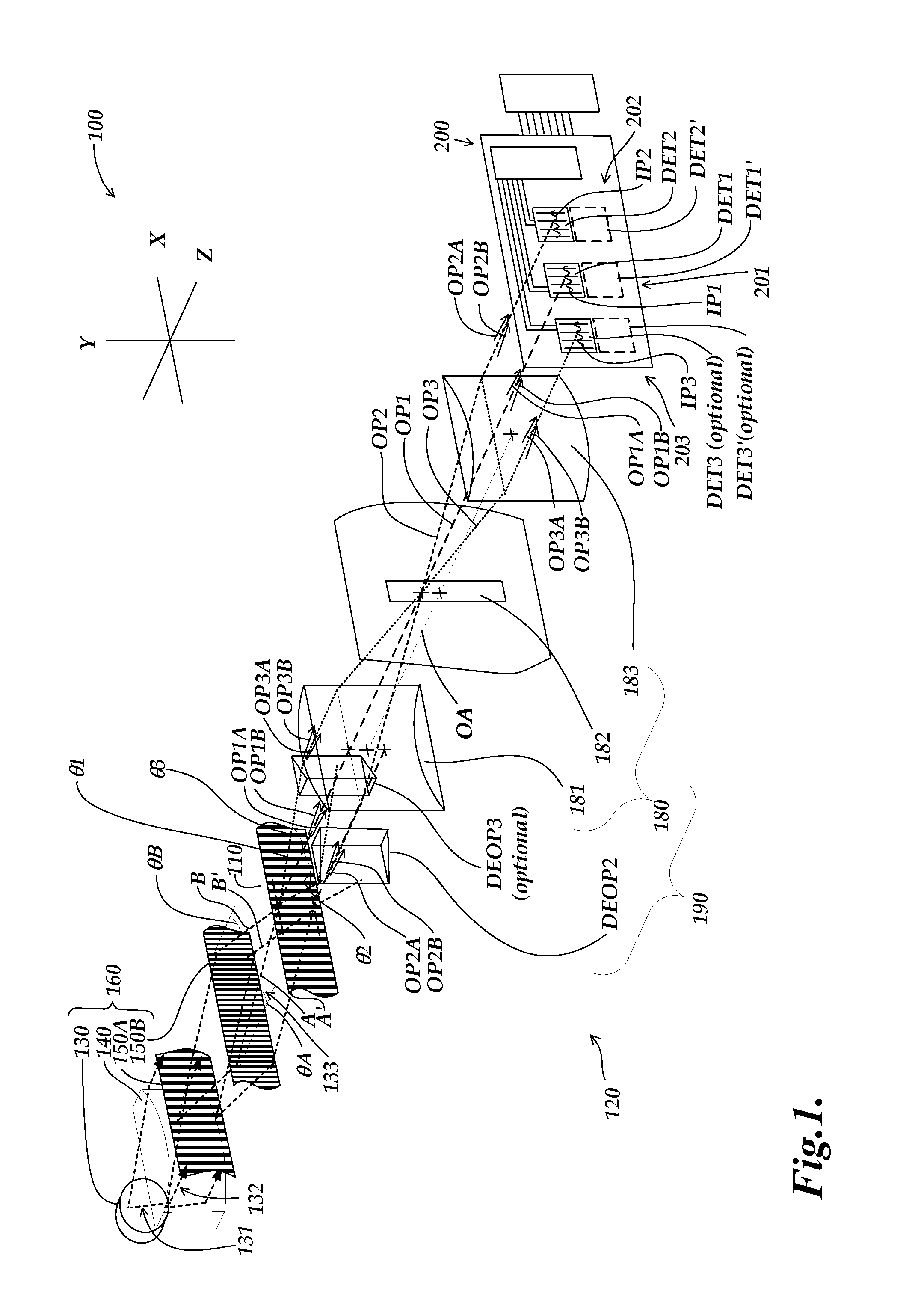
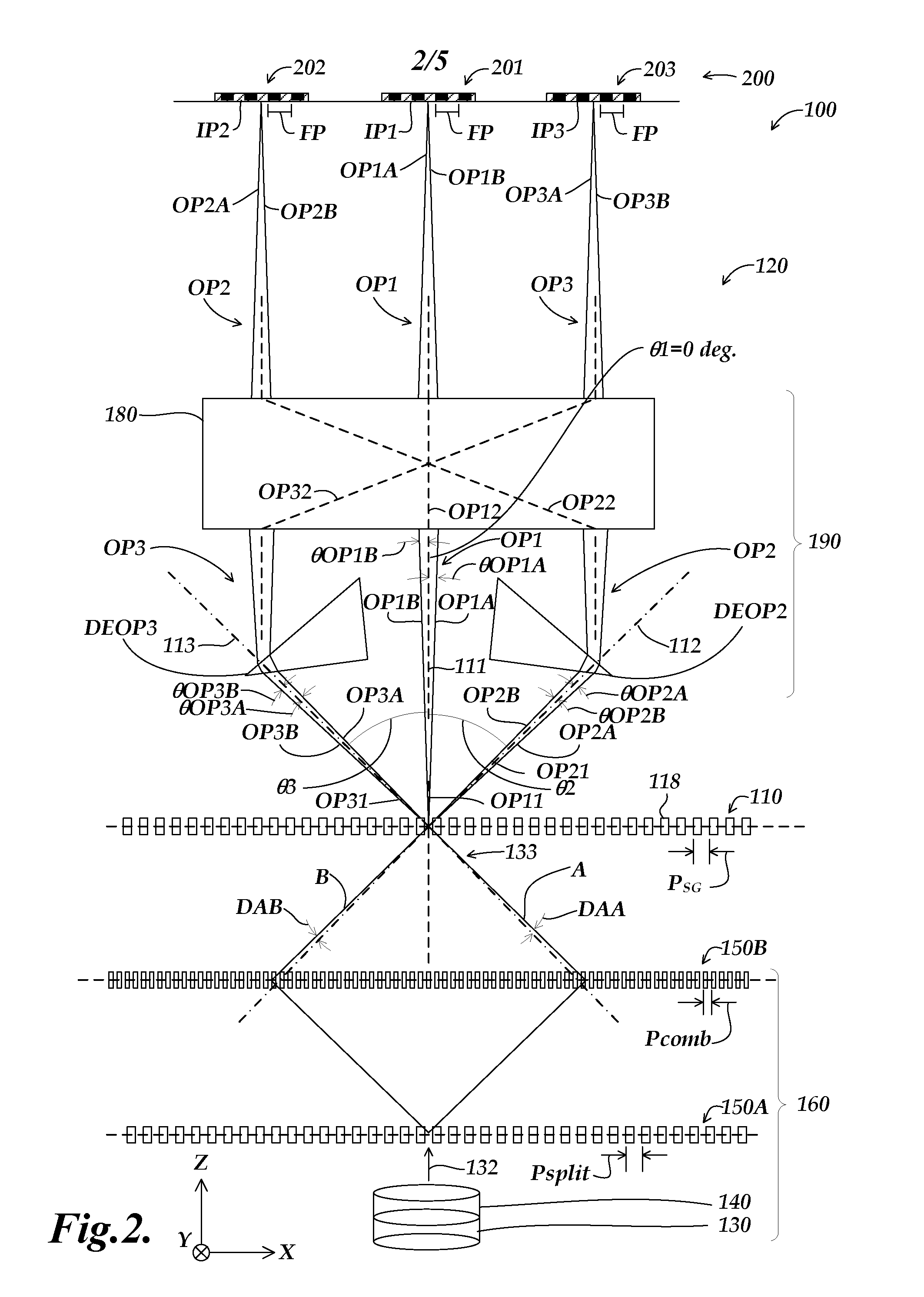
[0022]Referring to FIGS. 1 and 2, a displacement sensor 100 according to a first embodiment comprises a scale grating 110 and a scale light imaging configuration 120.
[0023]The scale grating 110 includes grating bars 118 disposed in an X direction and having a period PSG, which in some embodiments is 1 μm. Each of the grating bars 118 extends in a Y direction that is perpendicular to the X direction. The scale grating defines a set of diffraction planes 111, 112, and 113 that respectively correspond to a set of diffractive order angles θ1, θ2, and θ3 corresponding to a plane wave perpendicularly incident onto the scale grating 110. In this embodiment, θ1=0 degree, and θ2=−θ3. The diffraction plane 111 is perpendicular to the X direction, and diffraction planes 112 and 113 are symmetric with respect to the diffraction plane 111. In the embodiment, the scale grating 110 is a transmissive scale grating; however, a reflective scale grating can be used.
[0024]The scale light imaging config...
second embodiment
[0051]Referring to FIG. 4, a displacement sensor 300 according to a second embodiment differs from the displacement sensor 100 according to the first embodiment in that the telecentric imaging portion 180 of the displacement sensor 100 is a double telecentric imaging system, whereas the telecentric imaging portion 180′ of the displacement sensor 300 is a single telecentric imaging system including a lens 181′ and an aperture slit 182′. The remaining configurations of both displacement sensors 100 and 300 are the same.
third embodiment
[0052]Referring to FIG. 5, a displacement sensor 400 according to a third embodiment differs from the displacement sensor 100 according to the first embodiment in that in the first embodiment, the diffraction plane 111′ is perpendicular to the X direction, and diffraction planes 112′ and 113′ are symmetric with respect to the diffraction plane 111′, whereas in the third embodiment, the diffraction plane 111′ is perpendicular to the X direction, and the diffraction planes 112′ and 113′ are in parallel with each other. In addition, the displacement sensor 400 comprises a blocking element 175 which is positioned such that it blocks a +1 order diffraction component arising from the illumination light component A and a −1 order diffraction component arising from the illumination light component B. These components may interfere with scale light components along the optical path OP2′. The remaining configurations of both embodiments are the same.
PUM
 Abstract
Description
Claims
Application Information
 - R&D
- Intellectual Property
- Life Sciences
- Materials
- Tech Scout
- Unparalleled Data Quality
- Higher Quality Content
- 60% Fewer Hallucinations
Browse by: Latest US Patents, China's latest patents, Technical Efficacy Thesaurus, Application Domain, Technology Topic, Popular Technical Reports.
© 2025 PatSnap. All rights reserved.Legal|Privacy policy|Modern Slavery Act Transparency Statement|Sitemap|About US| Contact US: help@patsnap.com