Power distribution system connecting apparatus

a technology of power distribution system and connecting apparatus, which is applied in the direction of d dc source parallel operation, ac network circuit arrangement, etc., can solve the problems of high apparatus trouble, system side ill-influence, and high so as to prevent the ill-influence of trouble and reduce the load on the electric power source apparatus

Inactive Publication Date: 2012-12-13
HITACHI APPLIANCES INC
View PDF3 Cites 4 Cited by
  • Summary
  • Abstract
  • Description
  • Claims
  • Application Information

AI Technical Summary

Benefits of technology

[0010]Then, according to the present invention, an object thereof is to provide a (power distribution) system connecting apparatus for preventing the ill-influences of the trouble from being transferred to the system side, and also being able to deal with suppression of the reverse power flow, with reducing the load on each electric power source apparatus.

Problems solved by technology

However, the system connecting apparatus disclosed in the Patent Document 1 suppresses only a total amount of power generation within the consumer; but never describes therein a suppressing method for each electric power source apparatus.
Those fluctuations of the amount of power generation result into a load for the electric power source apparatus.
When the power generating apparatus shows the sign of trouble, a possibility that the apparatus falls into trouble is high, and there is also a possibility that ill-influences of the trouble may be transferred to the system side.

Method used


Image

  • Power distribution system connecting apparatus
  • Power distribution system connecting apparatus
  • Power distribution system connecting apparatus

Examples


embodiment 1

[0029]The present embodiment is one (1) embodiment of the system connecting apparatus according to the present invention. Explanation will be given on the present embodiment, by referring to FIGS. 1 to 5, 8 and 13 to 13.

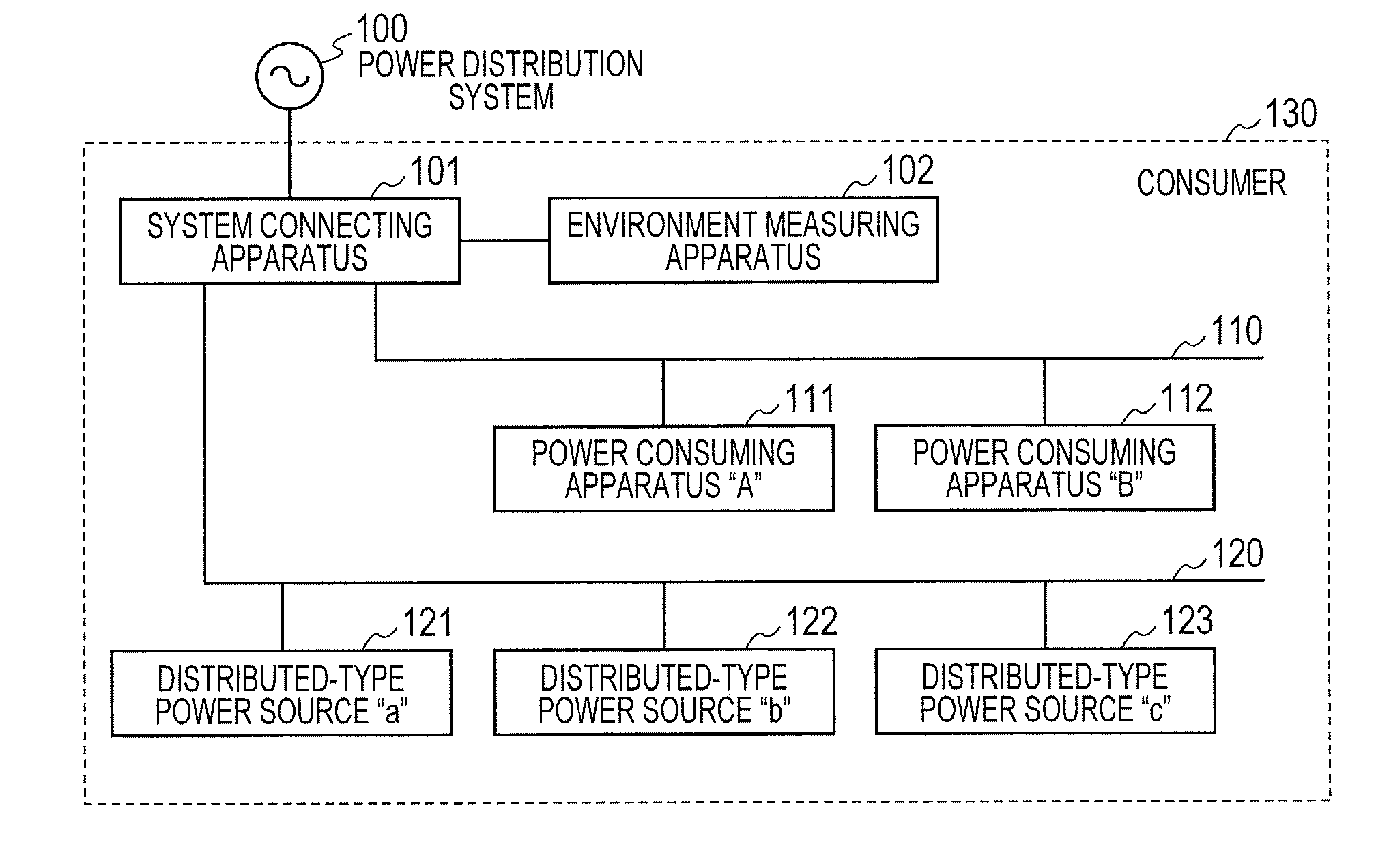
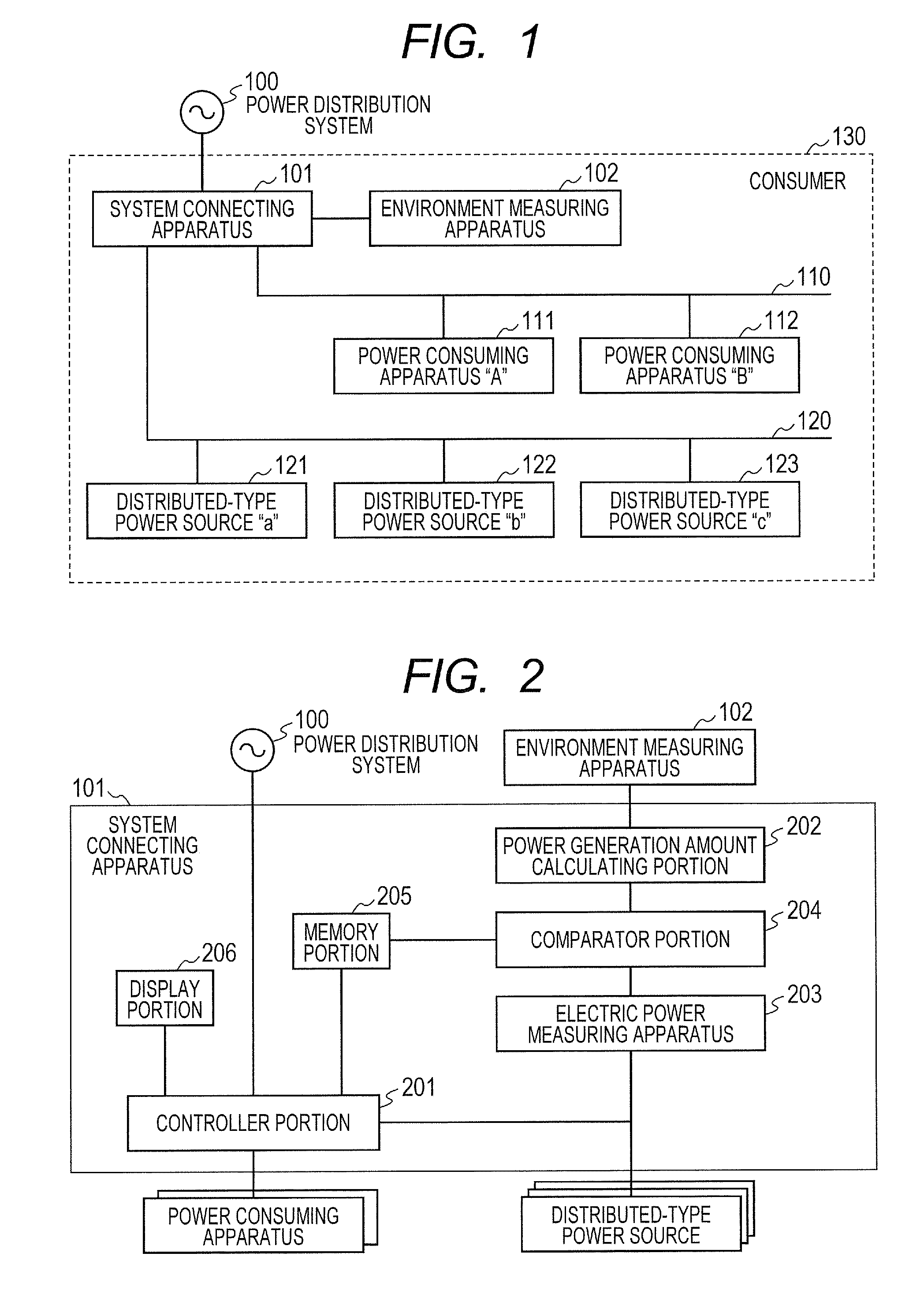
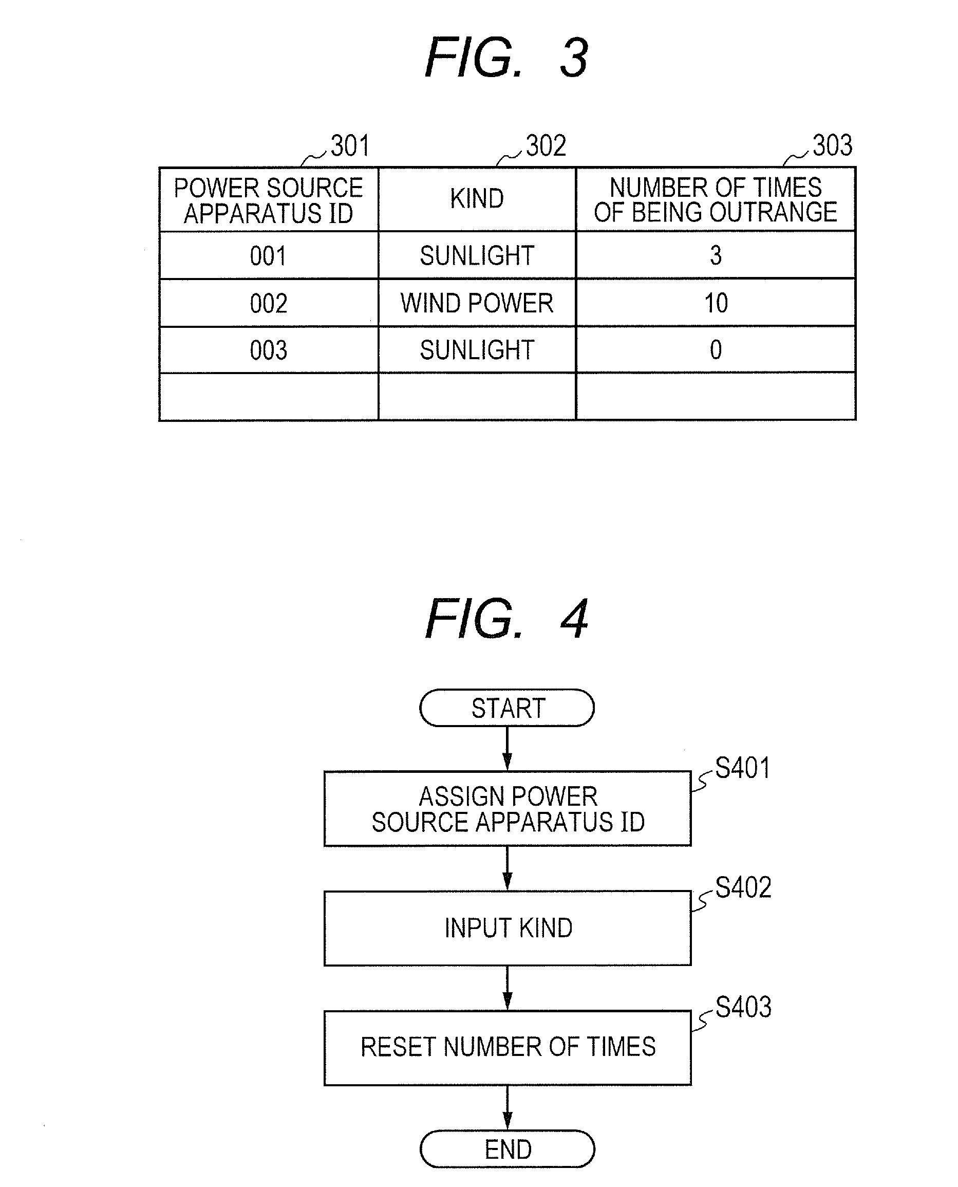
[0030]FIG. 1 is a view for showing the configuration of a (power distribution) system connecting apparatus between a (power distribution) system and a consumer, according to an embodiment, FIG. 2 is a block diagram of the system connecting apparatus according to the present embodiment, FIG. 3 is a view for showing a reliability estimation table according to the present embodiment, FIG. 4 is a flowchart for conducting registration process of the reliability estimation table, in the system connecting apparatus according to the present embodiment, FIG. 5 is a flowchart for conducting reliability estimation and parallel off, in the system connecting apparatus according to the present embodiment, FIG. 8 is a view for showing the reliable estimation table, obtained by exte...

embodiment 2

[0045]A present embodiment, comparing to the first embodiment, relates to the system connecting apparatus, in particular, in case where an instruction for suppressing or controlling an output (hereinafter, being called an “output suppression instruction”) is given, including an amount of suppression, for suppression of reverse power flow from the system side. However, the configuration of a system connecting system between the system and the consumers in the present embodiment is same to that shown in FIG. 1, a block diagram of the system connecting apparatus is same to that shown in FIG. 2, a reliability estimation table is same to that shown in FIGS. 3 and 8, a flowchart for executing the registration process of the reliability estimation table is same to that shown in FIG. 4, a view for showing a display on a display portion is same to that shown in FIG. 14, and an distributed-type power source enabled environment measuring apparatus table for making correspondence to an environm...

embodiment 3

[0051]A present embodiment relates, comparing to the first embodiment, to a system connecting apparatus for estimating the reliability with using a value obtained, while obtaining a measured value of the amount of power generation of the distributed-type power sources from the consumers neighboring with, but not doing calculating of the theoretical amount of power generation with using the measured value of the environment measuring apparatus. However, in the present embodiment, since a reliability estimation table is same to that shown in FIGS. 3 and 8, a flowchart for conducting the registering process of the reliability estimation table is same to that shown in 4, the figure for showing a display on the display portion is same to that shown in FIG. 13, the figure for showing a display screen is same to that shown in FIG. 14, and an distributed-type power source enabled environment measuring apparatus table for making correspondence to an environment measuring apparatus being suit...


PUM


Abstract

A power distribution system connecting apparatus comprises a power generation amount calculating portion for calculating a theoretical amount of power generation of the power source apparatus from an environment measurement value, a power measuring portion for measuring an amount of power generation of the power source apparatus, a comparator portion for comparing the calculation value of the power generation amount calculating portion and the measurement value of the power measuring portion, a memory portion for memorizing a result of comparison in the comparing portion, and a display portion for displaying a condition of the power source apparatus thereon; thereby providing the power distribution system connecting apparatus for enabling to deal with suppression of a reverse power flow, while preventing ill-influences due to troubles from being transferred to a system side.

Description

[0001]This application relates to and claims priority from Japanese Patent Application No. 2011-129773 filed on Jun. 10, 2011, the entire disclosure of which is incorporated herein by reference.BACKGROUND OF THE INVENTION[0002]The present invention relates to a power distribution system (hereinafter, being called by only “system”) linking or connecting apparatus.[0003]As the background of the present technical field, for example, Japanese Patent Laying-Open No. 2010-11705 (the following Patent Document 1) is already known. In this publication is described “for providing a system connecting apparatus, a system connecting system, a power transmission system and a controlling apparatus, for enabling fair reverse power flow among respective users and stabilization of voltages in the power distribution system (e.g., a bank), as the problem to be dissolved, a system connecting apparatus, to be connected with the power distribution system (e.g., the bank), to which AC electric power is sup...

Claims


Application Information

Patent Timeline
Patent Type & Authority Applications(United States)
IPC IPC(8): H02J3/00
CPCH02J3/382Y02E60/76Y04S40/22H02J2003/007H02J2203/20H02J2300/20H02J3/381Y02E60/00Y04S40/20H02J3/466
Inventor WAKABAYASHI, NOBORU
Owner HITACHI APPLIANCES INC
Why Eureka
Try Eureka