Injection molded control panel with in-molded decorated plastic film

a technology of plastic film and control panel, which is applied in the direction of display/control unit casings, printed circuit non-printed electric components association, electric apparatus casing/cabinet/drawer, etc., can solve the problems of many potential failure points of conventional control panel, switch, indicator, etc., and interconnection with circuit board failure, etc., to reduce complexity and cost

Active Publication Date: 2012-12-13
E2IP TECH INC
View PDF13 Cites 64 Cited by
  • Summary
  • Abstract
  • Description
  • Claims
  • Application Information

AI Technical Summary

Benefits of technology

[0007]A simplified control panel assembly that comprises two film layers bonded to either side of an injection molded resin and that vastly reduces the complexity and cost of, e.g., control assemblies is disclosed herein.
[0010]According to still another aspect, the circuit termination for interconnection remains integral to the circuit yet is made available to directly plug into a separate control board typically found in devices that would use this kind of input device or simply to a power source, should the unit be able to function independently of any other managing device. Total encapsulation of these films and the attached components, insures protection from moisture, water immersion, corrosion, dirt and physical damage, resulting in a significantly more reliable product than available today using prior art.

Problems solved by technology

As a result, there are many potential failure points in a conventional control panel.
For example, the switches, indicators, etc., can fail, the interconnects with the circuit boards can fail, the circuit boards themselves can fail, and so on.
Such conventional assemblies can also be expensive to manufacture due to all the different components and interconnects and associated assembly, especially if the control panel is part of a small product, uniquely shaped product, a product with complex controls and indicators, or some combination thereof, etc.

Method used


Image

  • Injection molded control panel with in-molded decorated plastic film
  • Injection molded control panel with in-molded decorated plastic film
  • Injection molded control panel with in-molded decorated plastic film

Examples


Embodiment Construction

.”

BRIEF DESCRIPTION OF THE DRAWINGS

[0012]Features, aspects, and embodiments are described in conjunction with the attached drawings, in which:

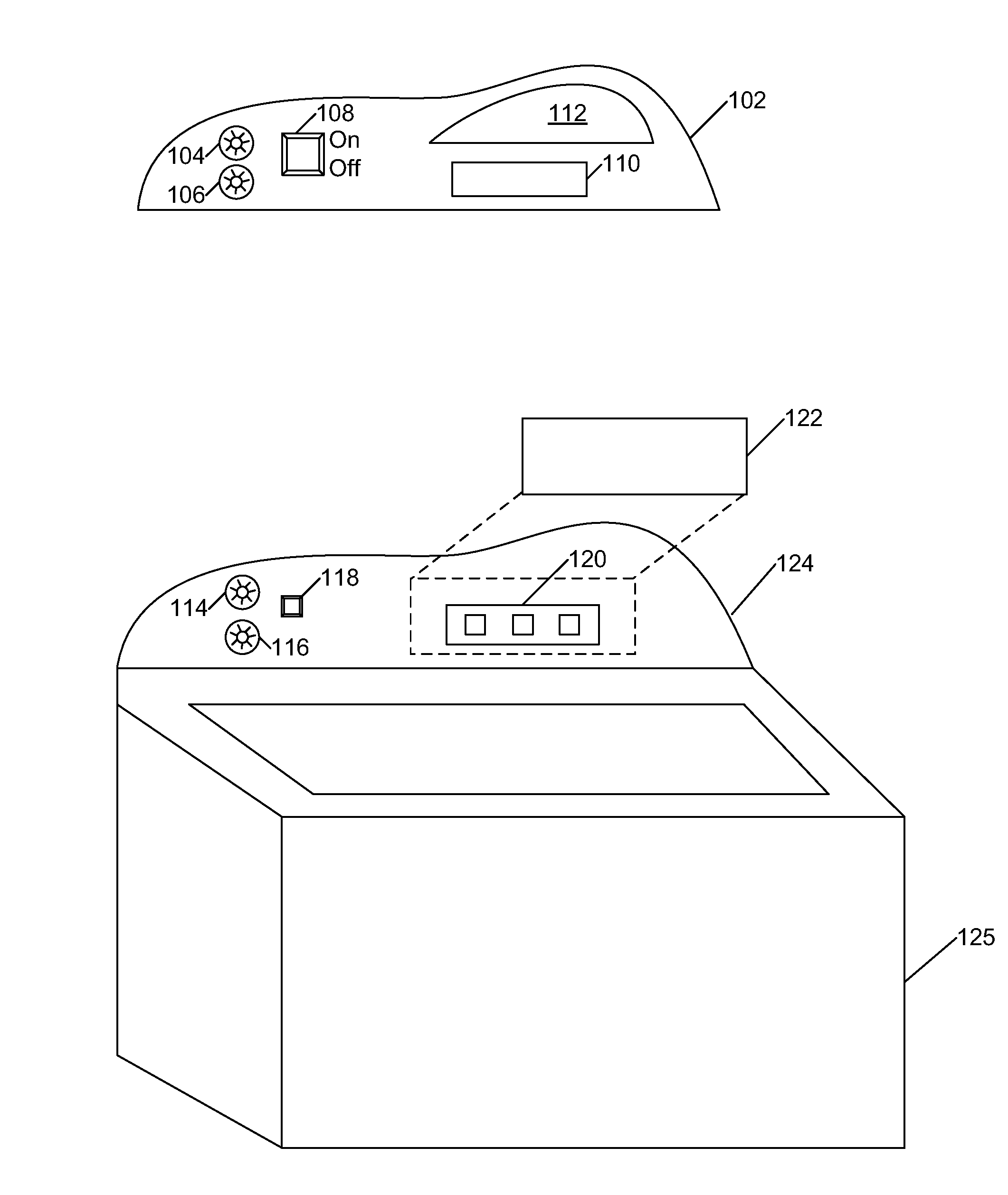
[0013]FIG. 1 is a diagram illustrating a conventional control panel assembly in accordance with one embodiment.

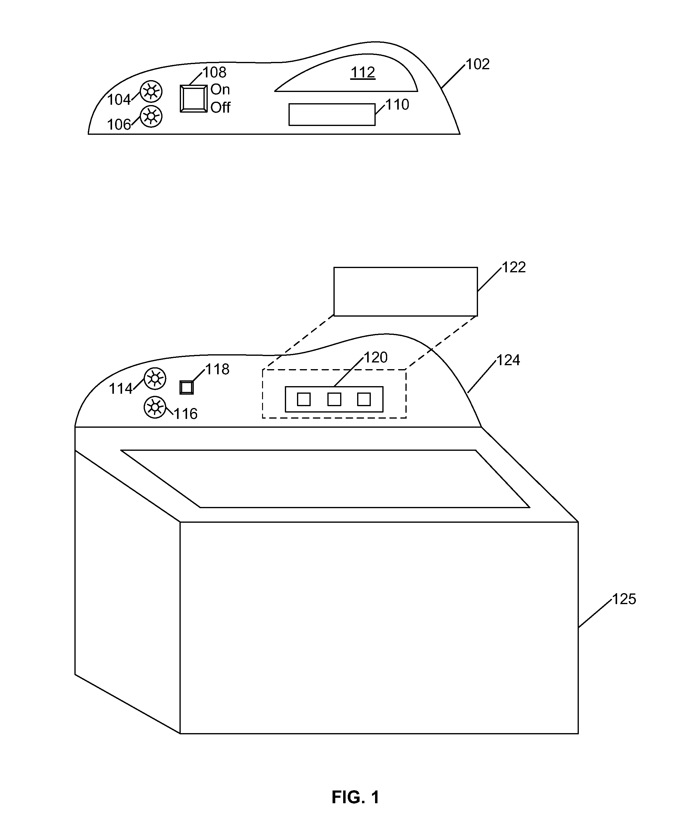
[0014]FIGS. 2A and 2B are diagrams illustrating an example control panel assembly in accordance with one embodiment.

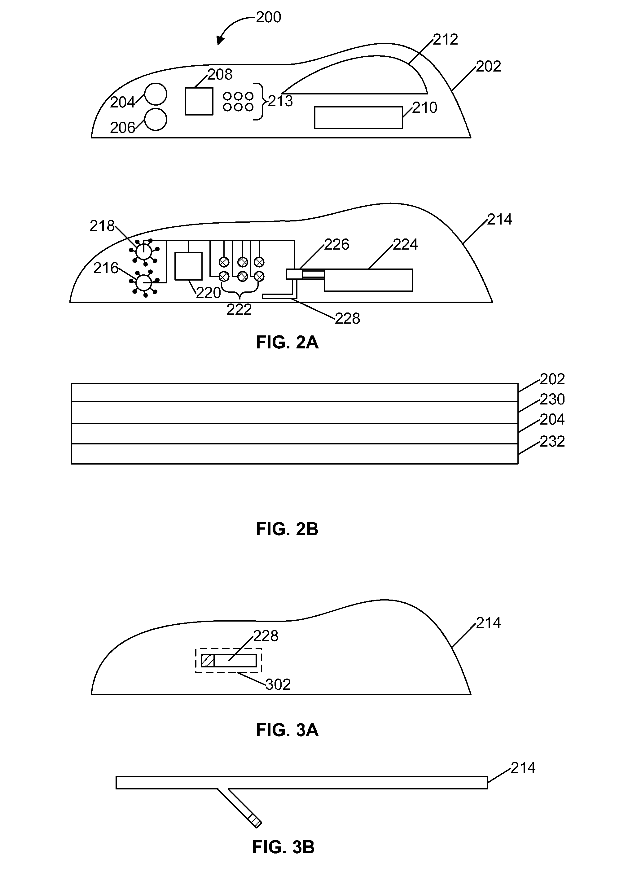
[0015]FIGS. 3A and 3B are diagrams illustrating an example circuit termination or connector in accordance with one embodiment.

[0016]FIG. 4 is a flowchart illustrating an example method for fabricating an injection molded control panel in accordance with one embodiment.

DETAILED DESCRIPTION

[0017]FIG. 1 is a diagram illustrating a conventional control panel assembly. For example, this control panel assembly may be the control panel for a washing machine. As such, the assembly can comprise an in-molded decorative plastic panel 102 that includes the graphics one would normally see on a washing machine control panel, such as g...


PUM

PropertyMeasurementUnit
total thicknessaaaaaaaaaa
thicknessaaaaaaaaaa

Abstract

Provided are systems and methods for a control assembly including: a first film that is in-molded that includes decorative graphics, a front surface and a rear surface; and a second film molded to the rear surface of the first film having a printed circuit that includes sensors, control circuits and interconnects and a front and rear surface.

Description

RELATED APPLICATIONS INFORMATION[0001]This application claims priority under 35 U.S.C. 119(e) to U.S. Provisional Patent Application Ser. No. 61 / 495,899, filed Jun. 10, 2011, and entitled “Injection Molded Control Panel with In-Molded Decorated Plastic Film,” and also claims priority under 35 U.S.C. 119(e) to U.S. Provisional Patent Application Ser. No. 61 / 495,901, filed Jun. 10, 2011, and entitled “Injection Molded Control Panel with In-Molded Decorated Plastic Film that Includes an Internal Connector,” both of which are incorporated herein by reference in their entirety as if set forth in full.BACKGROUND[0002]1. Technical Field[0003]The embodiments described herein are related to injection molding and in particular to methods of reducing the number of separate components and complexity of control panel assemblies.[0004]2. Related Art[0005]When injection molding a control panel, an in-molded decorative plastic film is often included. The molded control panel with the decorative pla...

Claims


Application Information

Patent Timeline
Patent Type & Authority Applications(United States)
IPC IPC(8): H05K7/00B32B38/00
CPCH05K5/0017H05K5/0243B29C45/14467B29C45/14639B29C45/14688B29C2045/14532Y10T29/49004H05K3/30H05K1/0298H05K2201/09818H05K2201/10507D06F39/005G02B6/0001H05K1/18B29C45/14H05K5/00D06F34/28H05K1/181H05K3/0014H05K1/189H05K1/16H05K3/12H05K3/284
Inventor MONCRIEFF, SCOTT
Owner E2IP TECH INC
Why Eureka
Try Eureka