Method & apparatus for optimizing data traffic path through a stacked switch lag configuration

a data traffic path and stacking switch technology, applied in data switching networks, frequency-division multiplexes, high-level techniques, etc., can solve the problems of data being dropped, single-chassis packet switches cannot support a limited number of line cards and ports, etc., and achieve the effect of optimizing the available stacking link bandwidth

Active Publication Date: 2012-12-13
DELL MARKETING CORP
View PDF5 Cites 46 Cited by
  • Summary
  • Abstract
  • Description
  • Claims
  • Application Information

AI Technical Summary

Benefits of technology

[0009]In light of the forgoing limitations to the bandwidth available on stacking links connecting two or more switches in a stacked switch configuration, it would be beneficial to distribute data ingressing to any of the switches comprising the stacking switch to LAG port members in a manner that optimizes the available stacking link bandwidth. In one embodiment, the bandwidth limitations imposed by stacking links on a stacked switch comprised of two or more individual switches connected to each in a ring or daisy chain topology are mitigated in a method that includes compiling a list of values associated with the relative co

Problems solved by technology

Single chassis packet switches can only support a limited number of line cards and ports.
Depending upon the bandwidth limitations of these stacking links, it i

Method used


Image

  • Method & apparatus for optimizing data traffic path through a stacked switch lag configuration
  • Method & apparatus for optimizing data traffic path through a stacked switch lag configuration
  • Method & apparatus for optimizing data traffic path through a stacked switch lag configuration

Examples


Embodiment Construction

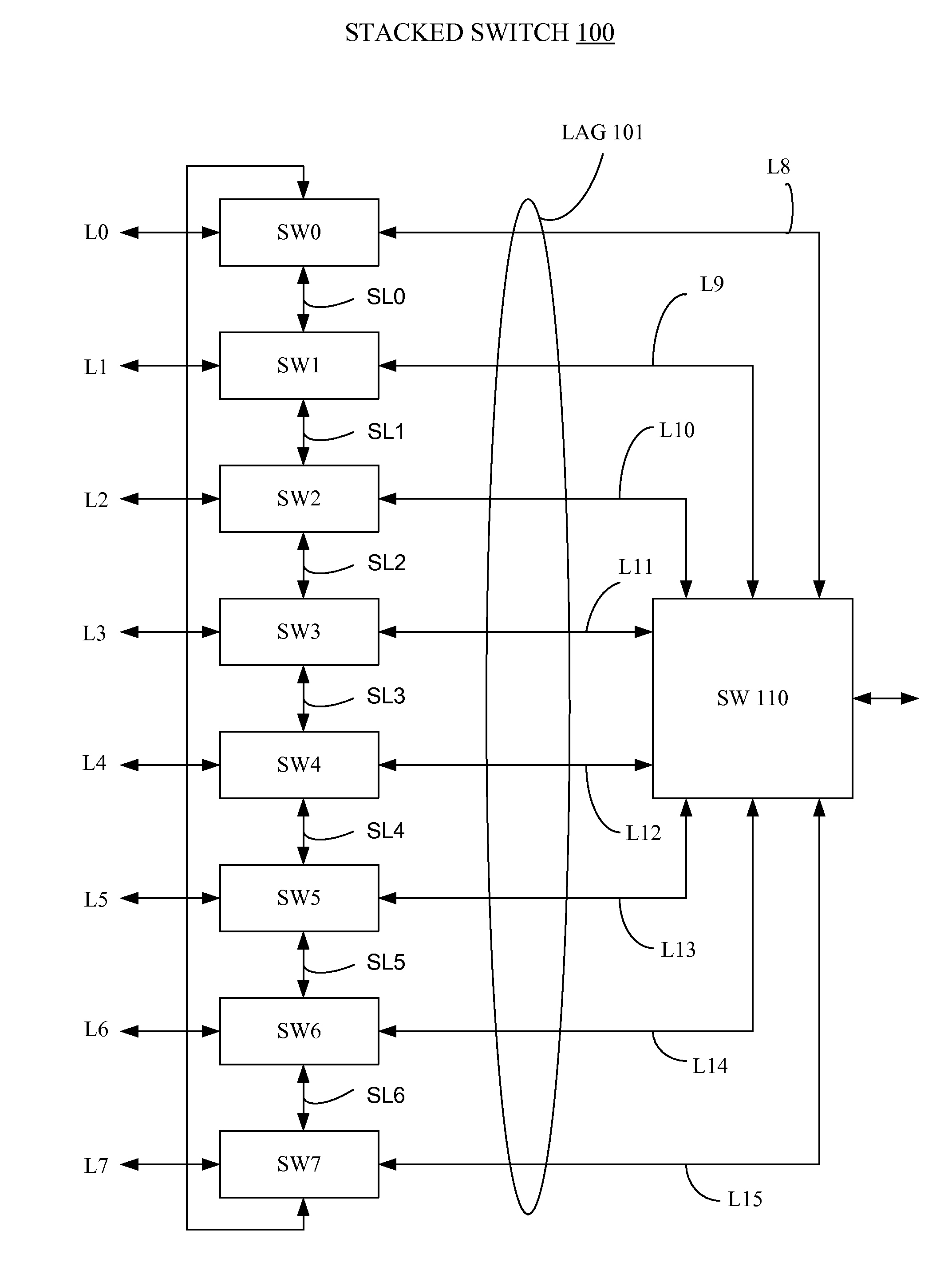
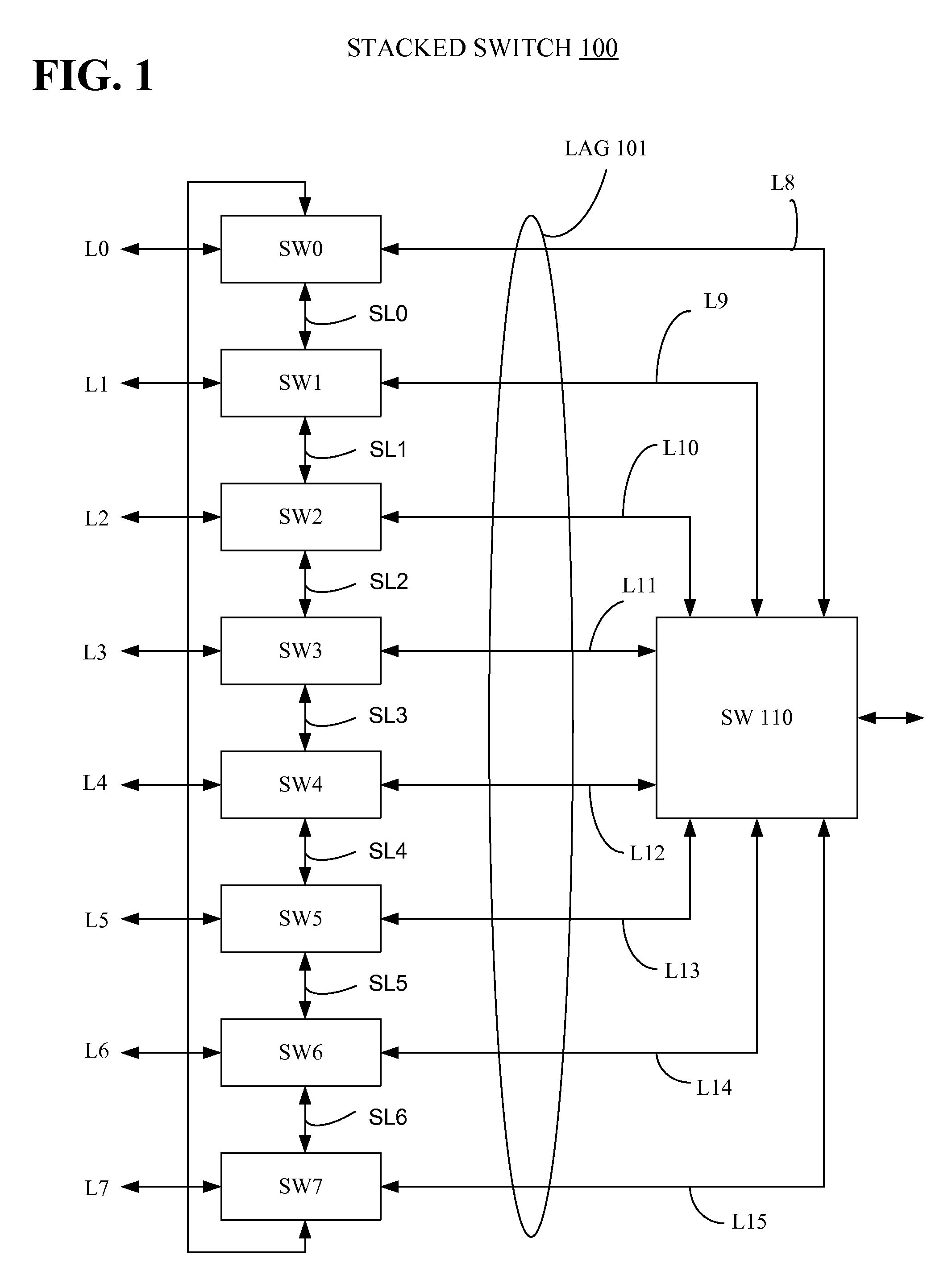
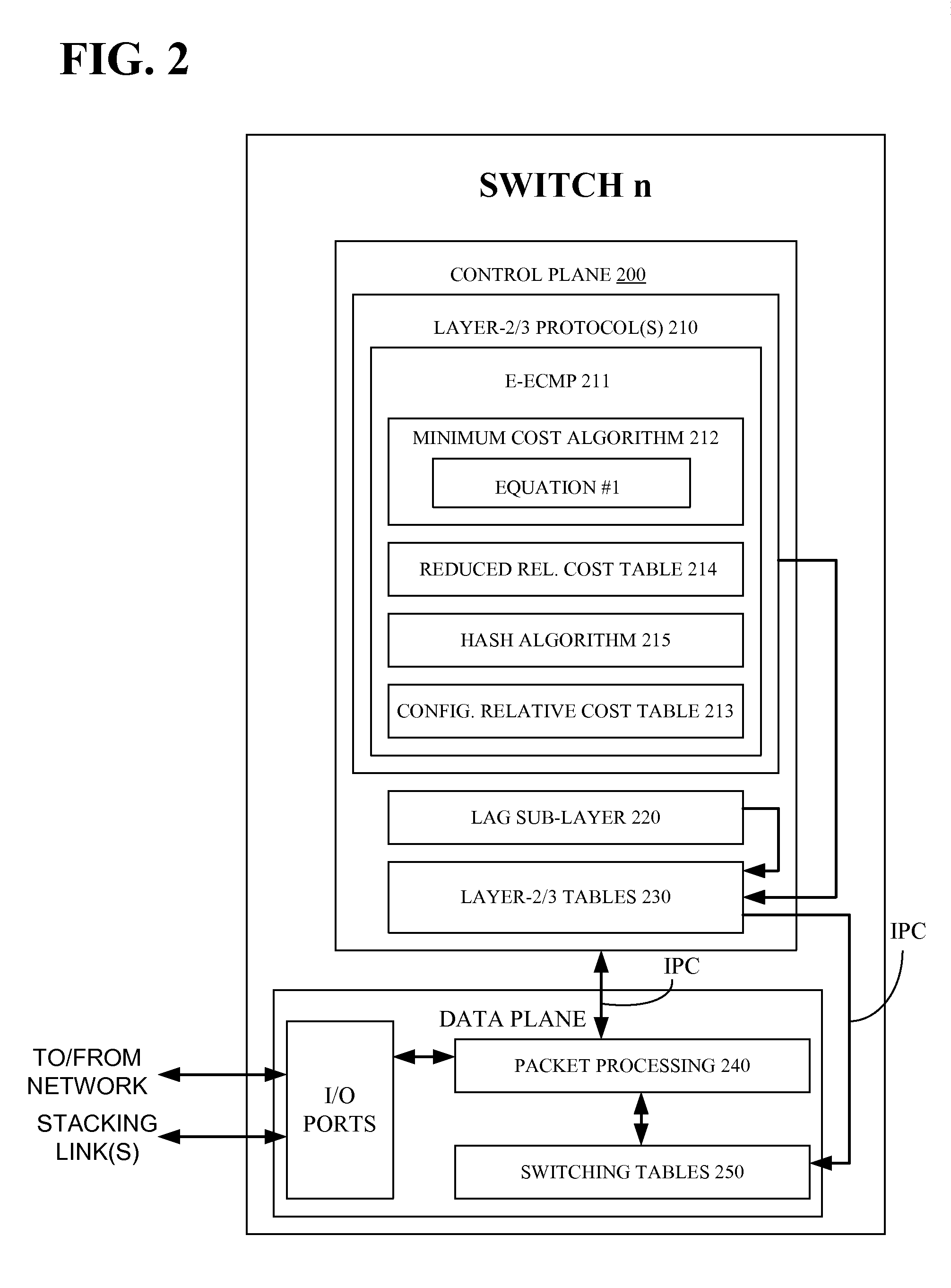
[0018]As described earlier in the background section, stacking links comprising a stacked switch with relatively low available bandwidth can be overwhelmed by network data flowing through a stacked switch. It was discovered, that it is possible to reduce / control the amount of traffic / data transmitted over the stacking links by limiting the number of stacking links that the traffic / data crosses from an ingress port to an egress port on the stacked switch. In one embodiment, an enhanced equal cost multipath (ECMP) routing technique is employed by each of the network switches comprising a stacked switch to reduce the number of stacking links that data ingressing to the stacked switch crosses before egressing from the switch. An embodiment of an enhanced ECMP routing technique is described with reference to FIG. 2.

[0019]FIG. 2 is a block diagram showing functionality comprising a network switch (SWn) that includes the enhanced ECMP routing technique described above. Network switch SWn c...


PUM


Abstract

A stacked switch includes two or more individual network switches connected to each other in a ring or daisy chain topology over stacking links, and at least one port on two or more of the individual switches comprising the stacked switch is a member of a LAG configured on the stacked switch. Each of the individual switches comprising the stacked switch include control plane and data plane functionality that operates to maintain switching tables and to process network data ingressing to the switch to determine how to forward the network data through the switch to an egress point. The control functionality included in each of the switches comprising the stacked switch also includes an enhanced ECMP functionality that operates to optimize the use of stacking link bandwidth on the stacking links connecting the two or more individual switches to each other.

Description

BACKGROUND[0001]1. Field of the Invention[0002]The present disclosure relates generally to packet network devices such as switches that are configured in a stacked relationship to each other and which are configured to support a link aggregation group. This disclosure relates more particularly to methods for selecting a egress port to use for network traffic switched through the stacked switch over the link aggregation group.[0003]2. Description of Related Art[0004]Single chassis packet switches can only support a limited number of line cards and ports. Some vendors provide special link cards or “back-end” ports that can be used to connect or stack two or more separate switches together to form a stacked system that in at least some ways acts with peer devices like a single larger chassis. U.S. patent application Ser. No. 12 / 828,514 entitled “Multiple Chassis Stacking using Front-End Ports” which was filed Jul. 1, 2010 and assigned to Force 10 Networks, Inc. describes a method and a...

Claims


Application Information

Patent Timeline
IPC IPC(8): H04L12/24
CPCH04L41/0826Y02B60/33H04L49/45H04L45/245Y02D30/50
Inventor RAJAMANICKAM, MURALIKRISHNANRAJAMANICKAM, SAMPATHKUMAR
Owner DELL MARKETING CORP
Why Eureka
Try Eureka