[0045]Providing the signalling per
physical layer pipe on layer 1 requires less transmission resources than signalling of the information in each baseband frame mapped to a physical layer
pipe. Moreover, by signalling the information related to a physical layer pipe only within the layer 1 signalling and deriving the configuration for the baseband frames accordingly instead of explicit signalling in the baseband frame header avoids inconsistencies in setting corresponding parameters in different structures. Another
advantage of the present invention lays in the fact that the robustness for the different physical layer pipes—of which one or more carry layer 1 signalling partly or completely—as well as for the pre-amble symbols that might carry layer 1 signalling partly or completely can be chosen independently from each other. This is not the case for signalling in the baseband frame headers since the robustness of the baseband frame transmission depends on the configuration of the particular physical layer pipe. Thus, thanks to moving a part of the baseband frame header signalling to the layer 1 signalling, the present invention enables applying the desired robustness for both, content and PLP-specific signalling, separately.
[0046]In accordance with an aspect of the present invention, a method for transmitting, in a digital broadcast network using a plurality of physical layer pipes (including the case of a single physical layer pipe), digital
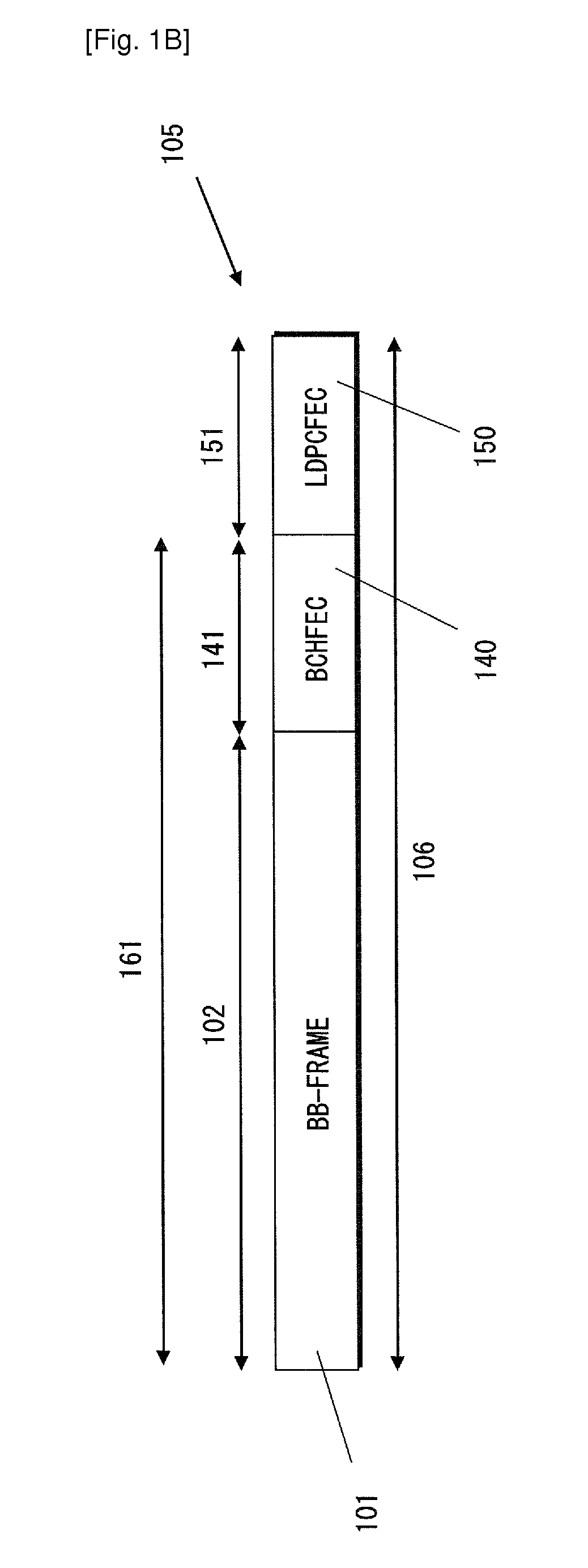
broadcast data encapsulated into one or more baseband frames is provided. Each baseband frame has a header of a predefined format. The physical layer
forward error correction coding is applied to the baseband frames and mapped on at least one physical layer pipe. The method comprises configuring a parameter of a physical layer pipe and applying the parameter settings to each baseband frame transmitted within said physical layer pipe. The parameter indicates either of an input stream format, a single or a
multiple input stream, constant or variable coding and modulation, presence of input stream synchronization, presence of null packet deletion, or input stream identifier. The method further includes transmitting the configured parameter within physical layer signalling related to said physical layer pipe, and transmitting within said physical layer pipe baseband frames that do not include in their headers the configured parameter.
[0047]In accordance with another aspect of the present invention, a method for receiving, in a digital broadcast network using a plurality of physical layer pipes (including the case of a single physical layer pipe), digital
broadcast data encapsulated into one or more baseband frames is provided. Each baseband frame has a header of a predefined format. The physical layer
forward error correction coding is applied to the baseband frames and demapped from at least one physical layer pipe. The method comprises receiving a parameter describing the configuration of a physical layer pipe within layer 1 signalling related to said physical layer pipe, the parameter indicating either of an input stream format, a single or a
multiple input stream, constant or
adaptive coding and modulation, presence of input stream synchronization, presence of null packet deletion, or input stream identifier. The method further comprises decoding the parameter of said physical layer pipe and applying the signalled configuration to each baseband frame received within said physical layer pipe, and receiving within said physical layer pipe baseband frames that do not include in their headers the configured parameter.
[0048]In accordance with still another aspect of the present invention, an apparatus is provided for transmitting, in a digital broadcast network using a plurality of physical layer pipes (including the case of a single physical layer pipe), digital
broadcast data encapsulated into one or more baseband frames. Each baseband frame has a header of a predefined format. The physical layer
forward error correction coding is applied to the baseband frames and mapped on at least one physical layer pipe. The apparatus comprises a parameter setting unit for configuring a parameter of a physical layer pipe and applying the parameter settings to each baseband frame transmitted within said physical layer pipe, the parameter indicating either of an input stream format, a single or a multiple input stream, constant or
adaptive coding and modulation, presence of input stream synchronization, presence of null packet deletion, or input stream identifier. The apparatus further comprises a signalling transmitting unit for transmitting the configured parameter within physical layer signalling related to said physical layer pipe, and a data transmitting unit for transmitting within said physical layer pipe baseband frames that do not include in their headers the configured parameter.
[0049]In accordance with still another aspect of the present invention, an apparatus is provided for receiving, in a digital broadcast network using a plurality of physical layer pipes (including the case of a single physical layer pipe), digital broadcast data encapsulated into one or more baseband frames. Each baseband frame has a header of a predefined format. The physical layer forward
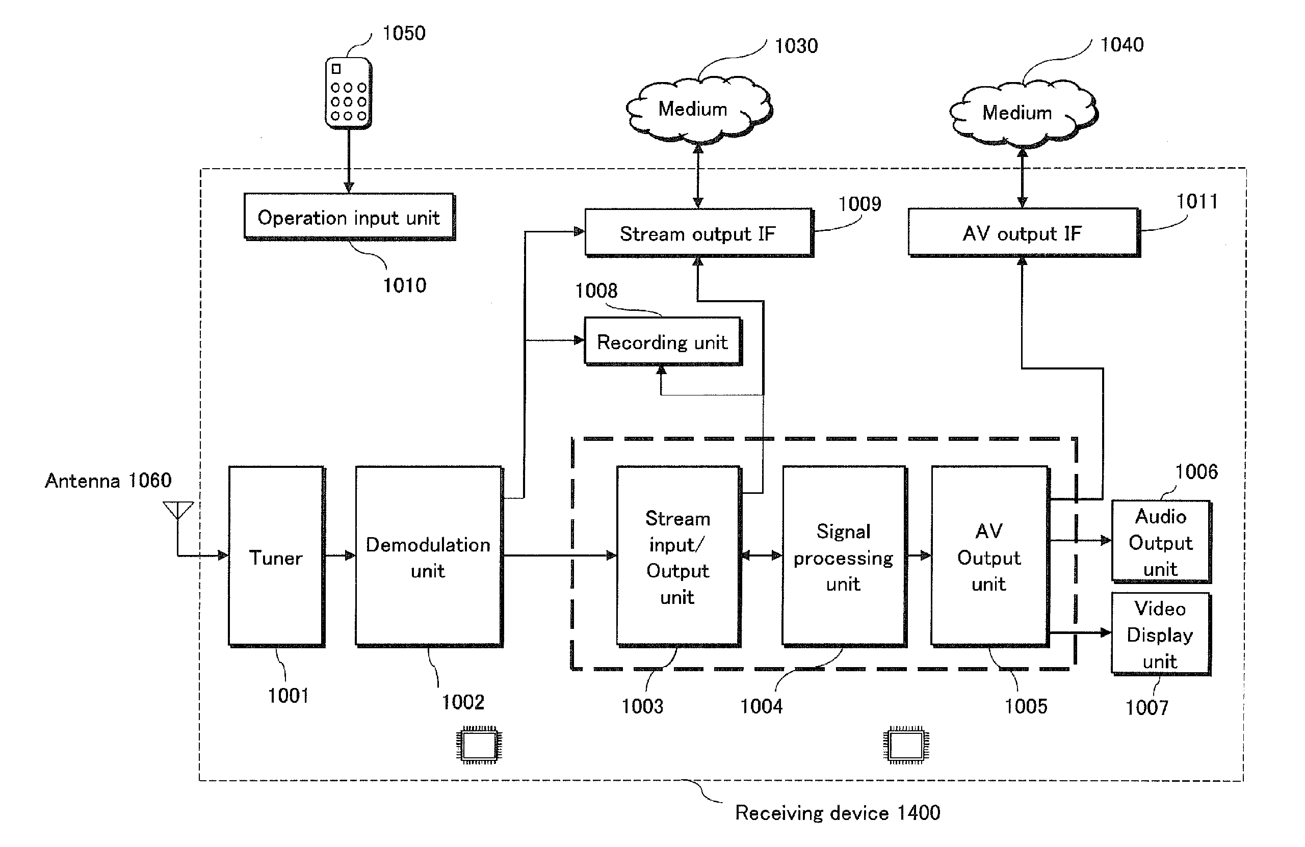
error correction coding is applied to the baseband frames and demapped from at least one physical layer pipe. The receiving apparatus includes a signalling receiving unit for receiving a parameter describing the configuration of a physical layer pipe within physical layer signalling related to said physical layer pipe, the parameter indicating either of an input stream format, a single or a multiple input stream, constant or adaptive coding and modulation, presence of input stream synchronization, presence of null packet deletion, or input stream identifier. The apparatus further comprises a PLP determining unit for decoding the parameter of said physical layer pipe and applying the signalled configuration to each baseband frame received within said physical layer pipe, and a data receiving unit for receiving within said physical layer pipe baseband frames that do not include in their headers the configured parameter. Note that the “receiving apparatus” may be embodied as a “receiver” or a “receiving device” described below in the embodiments of the present invention.
[0050]Preferably, each of the parameters indicating an input stream format (220), presence of input stream synchronization, presence of NULL packet deletion, and input stream identifier are signalled within the layer 1 signalling. Carrying all these parameters within the layer 1 signalling allows for header
size reduction of baseband frames, thus improving considerably the transmission efficiency.


