Bicycle electrical component control system

Active Publication Date: 2012-12-13
SHIMANO INC
View PDF4 Cites 24 Cited by
  • Summary
  • Abstract
  • Description
  • Claims
  • Application Information

AI Technical Summary

Benefits of technology

[0011]Thus, in such a case, an operation mode that corresponds with the state of operation of the electrical bicycle components is selected from three or more operation modes based on the state of operation of the electrical bicycle components. Causing the electric bicycle to operate in the selected operation mode makes it possible to control the electrical bicycle components in an appropriate manner according to the state of operation of the electrical bicycle components.
[0016]In accordance with a sixth aspect of the present disclosure, the bicycle electrical component control system of any of the first through fifth aspects is further configured such that the control part switches and selects the current operation mode based on a predetermined sequence. In such a circumstance, the control part switches and selects the operation mode based on a predetermined sequence for switching the operation mode to each of the operation modes. For example, a switching path for switching the operation mode from one operation mode to another operation mode is set based on a predetermined sequence, therefore making it possible to switch the operation mode in a smooth and appropriate manner. This setting also makes it possible to eliminate unnecessary control, making it possible to reduce the load on the control part during processing.

Problems solved by technology

If operation of all electrical components is stopped merely because some of the electrical bicycle components are not operating normally, there is a possibility of not being able to take any advantage of the merits of power-assisted bicycles.
Also, in a circumstance in which some of the electrical bicycle components stop operating normally, if all electrical components, including the electrical bicycle components that are not operating normally, are allowed to continue to operate, there is a possibility of a fault occurring in electrical components that are operating normally.

Method used


Image

  • Bicycle electrical component control system
  • Bicycle electrical component control system
  • Bicycle electrical component control system

Examples


Embodiment Construction

[0025]Selected embodiments of the present invention will now be explained with reference to the drawings. It will be apparent to those skilled in the art from this disclosure that the following descriptions of the embodiments of the present invention are provided for illustration only and not for the purpose of limiting the invention as defined by the appended claims and their equivalents.

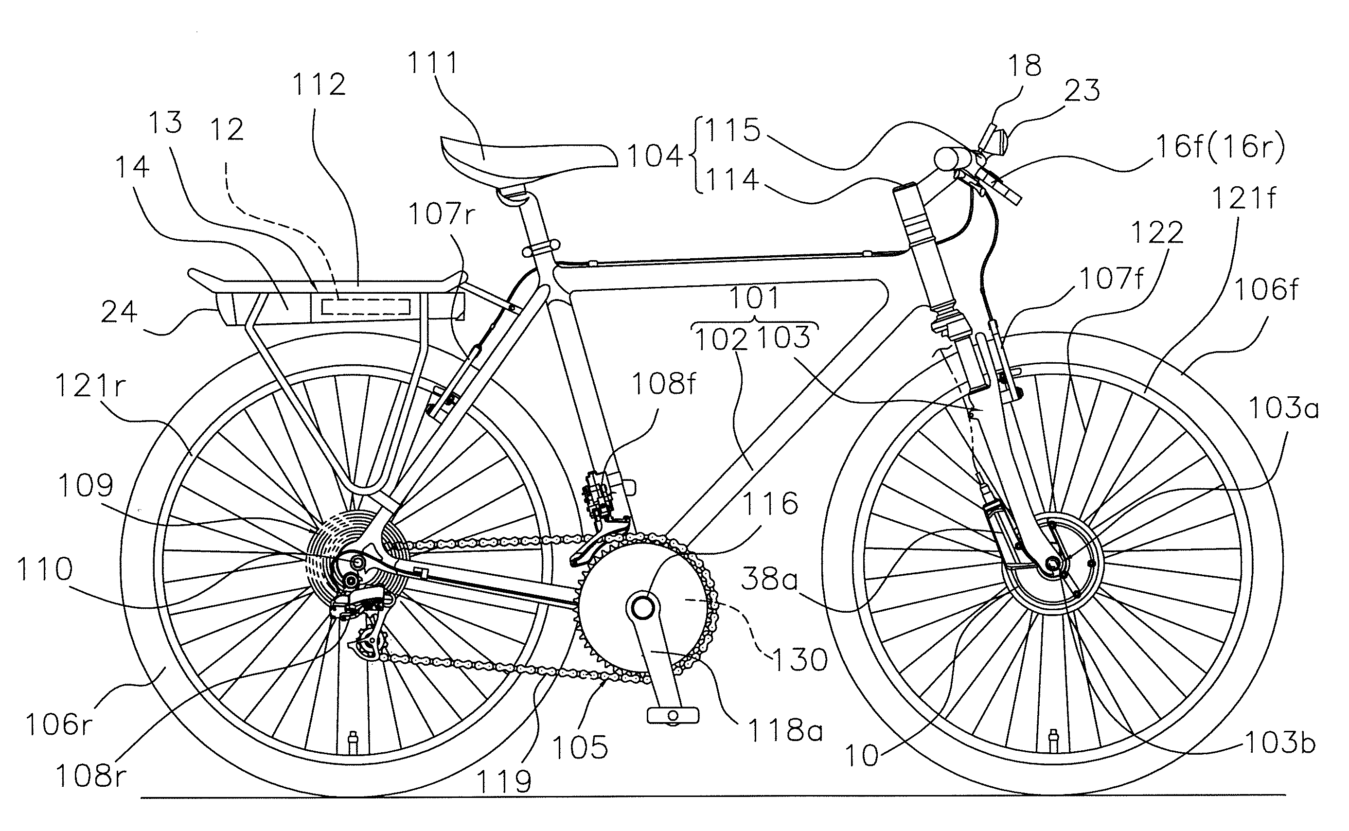
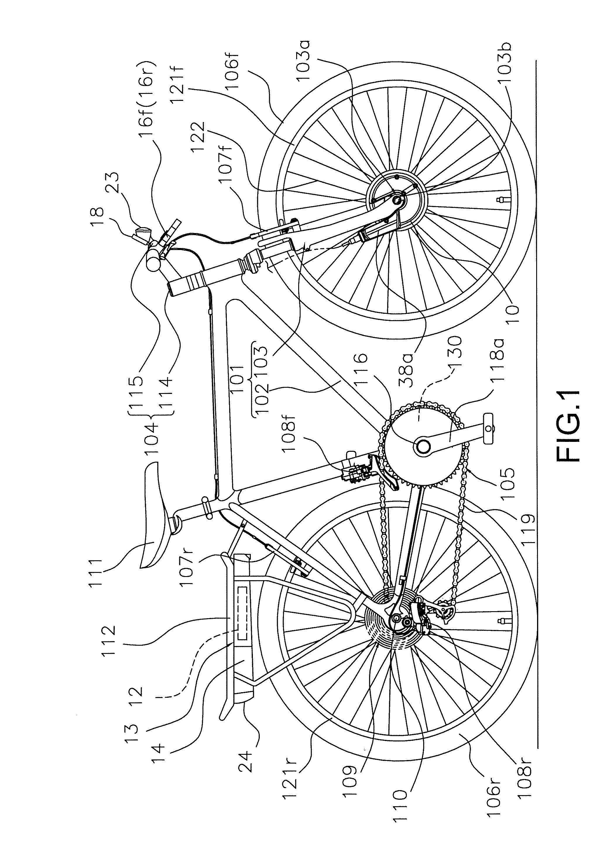
[0026]As shown in FIG. 1, a bicycle is illustrated which is equipped with a power-assisted bicycle in which human-powered driving is assisted by a motor-integrated hub or motor unit 10 in accordance with one illustrated embodiment. In the following description, the terms “left” and “right” of the bicycle are defined so that when the bicycle is viewed from the rear, the rightward direction is defined as the right, and the leftward direction is defined as the left.

[0027]The bicycle includes a frame 101 having a frame body 102 and a front fork 103 with a handle part 104. The bicycle further includes a...


PUM


Abstract

An electrical component control system is provided for controlling a plurality of electrical components that can be installed on an electric bicycle in which human-powered driving is assisted by a motor. The bicycle electrical component control system basically includes a control part that sets a current operation mode from at least three operation modes based on an operating state of each of the electrical bicycle components. The control part controls the electrical bicycle components in accordance with the current operation mode that was selected.

Description

CROSS-REFERENCE TO RELATED APPLICATIONS[0001]This application claims priority under 35 U.S.C. §119 to Japanese Patent Application No. 2010-134553, filed Jun. 11, 2010. The entire disclosure of Japanese Patent Application No. 2010-134553 is hereby incorporated herein by reference.BACKGROUND OF THE INVENTION[0002]1. Field of the Invention[0003]The present invention relates to a bicycle electrical component control system, and in particular to a bicycle electrical component control system for controlling a plurality of electrical components that can be installed on an electric bicycle in which human-powered driving is assisted by a motor.[0004]2. Background Information[0005]There are known in the art power-assisted bicycles, in which human-powered driving of a bicycle is assisted by an electric motor (for example, see JP-A 2005-304283). In a conventional power-assisted bicycle of such description, when the rider selects the assist mode, the driving force applied by the rider is assiste...

Claims


Application Information

Patent Timeline
IPC IPC(8): B62M6/45
CPCB62M6/45Y02T10/642B60L7/14B60L7/26B60L11/007B60L11/1803B60L11/1877B60L15/2009B60L2200/12B60L2220/44B60L2240/423B60L2250/16B60L2250/24Y02T10/7005Y02T10/705Y02T10/7275B60L2240/12B60L50/20B60L50/51B60L50/66Y02T10/64Y02T10/70Y02T10/72
Inventor SAIDA, TAKAO
Owner SHIMANO INC
Why Eureka
Try Eureka