Asymmetrical Combined Cycle Power Plant

a combined cycle and power plant technology, applied in the direction of machines/engines, mechanical equipment, transportation and packaging, etc., can solve the problems of less efficient and relatively more productive second engines than the first, and achieve the effect of less efficient and more productiv

Inactive Publication Date: 2012-12-20
GENERAL ELECTRIC CO
View PDF5 Cites 23 Cited by
  • Summary
  • Abstract
  • Description
  • Claims
  • Application Information

AI Technical Summary

Benefits of technology

[0004]A combined cycle power plant includes a first engine, a second engine, a first heat recovery steam generator, a second heat recovery steam generator, and a steam turbine. The second engine is relatively more productive but less efficient than the first engine. The first engine generates a first exhaust gas, and the second engine generates a second exhaust gas. The first heat recovery steam generator transfers excess energy from the first exhaust gas to a first flow of water, creating a first flow of steam. The second heat recovery steam generator transfers excess energy from the second exhaust gas to a second flow of water, creating a second flow of steam. The second heat recovery steam generator further transfers excess energy from the second exhaust gas to the first flow of steam and the second flow of steam, creating a flow of superheated steam. The steam turbine receives the flow of superheated steam from the second heat recovery steam generator.

Problems solved by technology

The second engine is relatively more productive but less efficient than the first engine.

Method used


Image

  • Asymmetrical Combined Cycle Power Plant
  • Asymmetrical Combined Cycle Power Plant
  • Asymmetrical Combined Cycle Power Plant

Examples


Embodiment Construction

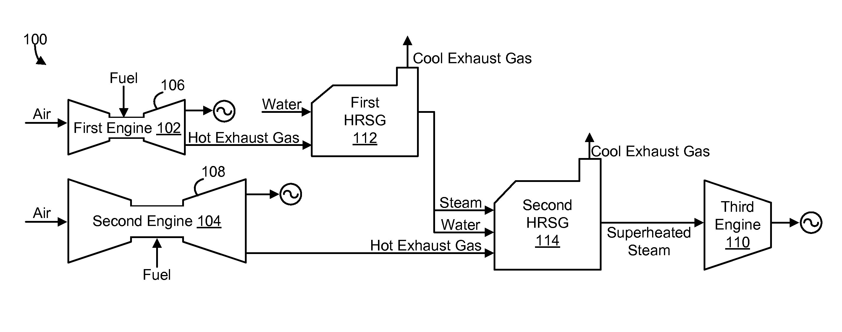
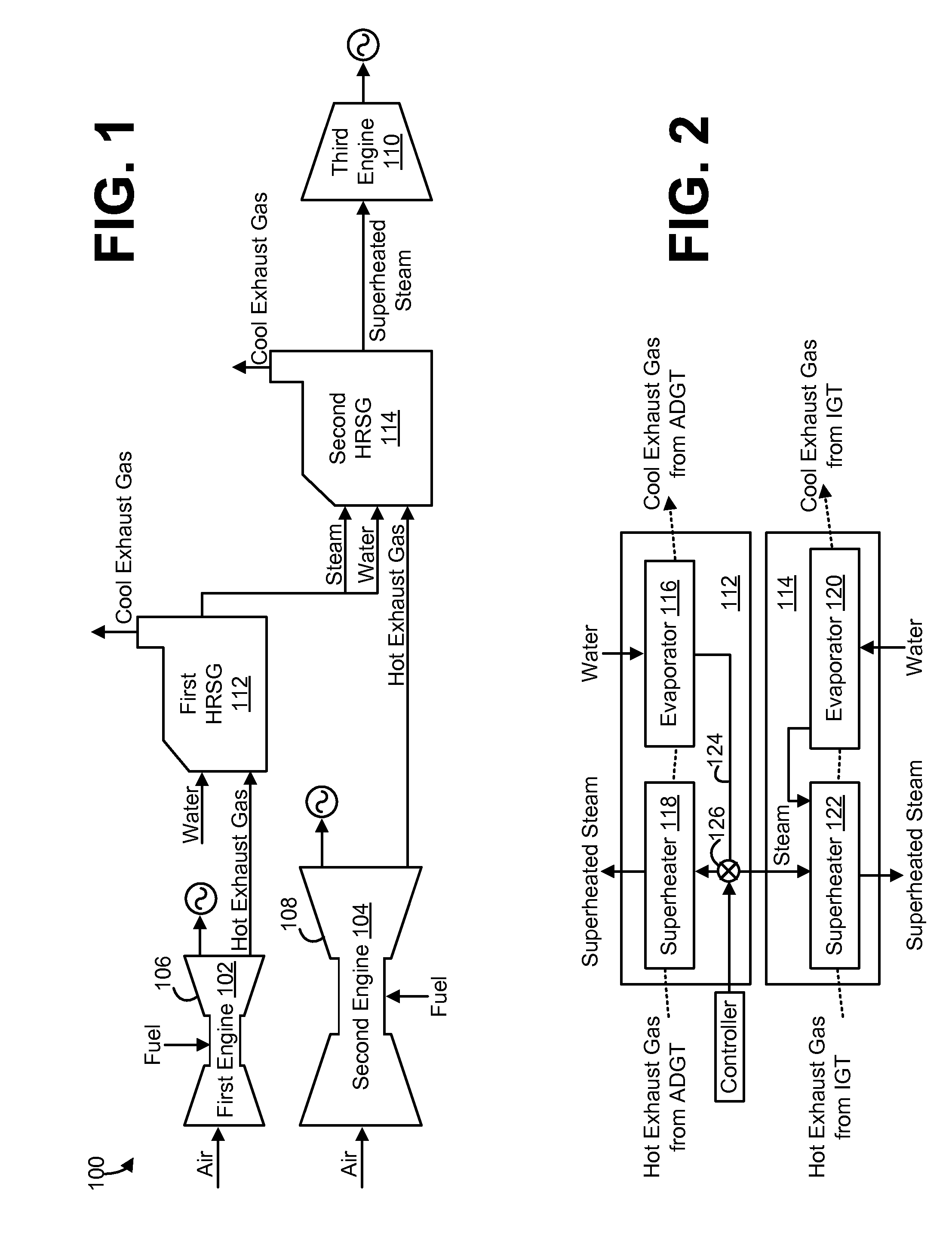
[0010]Described below are embodiments of an asymmetrical combined cycle power plant that employs two different topping cycle engines in combination with a single bottoming cycle engine. The two topping cycle engines are different from each other in a manner that causes one of the topping cycle engines to be more productive but less efficient than the other topping cycle engine. The two topping cycle engines are thermodynamically coupled to the bottoming cycle engine by way of a heat recovery system. The heat recovery system relies more heavily on the less efficient topping cycle engine to feed the bottoming cycle engine, thereby increasing the efficiency of the overall power plant.

[0011]For the purposes of this disclosure, the term “topping cycle engine” generally refers to an engine within the combined cycle power plant that generates waste energy that is recaptured for use in another portion of the combined cycle power plant. The term “bottoming cycle engine” generally refers to a...


PUM


Abstract

A combined cycle power plant includes a first engine, a second engine, a first heat recovery steam generator, a second heat recovery steam generator, and a steam turbine. The second engine is relatively more productive but less efficient than the first engine. The first engine generates a first exhaust gas, and the second engine generates a second exhaust gas. The first heat recovery steam generator transfers excess energy from the first exhaust gas to a first flow of water, creating a first flow of steam. The second heat recovery steam generator transfers excess energy from the second exhaust gas to a second flow of water, creating a second flow of steam. The second heat recovery steam generator further transfers excess energy from the second exhaust gas to the first flow of steam and the second flow of steam, creating a flow of superheated steam. The steam turbine receives the flow of superheated steam from the second heat recovery steam generator.

Description

TECHNICAL FIELD[0001]The present disclosure generally relates to a combined cycle power plant, and more particularly relates to a combined cycle power plant having two different gas turbines.BACKGROUND OF THE INVENTION[0002]A combined cycle power plant utilizes a gas turbine and a steam turbine in combination to produce power. The power plant is arranged such that the gas turbine is thermally connected to the steam turbine through a heat recovery steam generator (“HRSG”). The HRSG employs heat from the exhaust gases of the gas turbine to create steam for expansion in the steam turbine. The primary efficiency of the combined cycle arrangement is the utilization of the otherwise wasted heat from the gas turbine exhaust gases.[0003]Some combined cycle power plants employ a number of gas turbines. Each gas turbine may be thermally coupled to the same HRSG, or each gas turbine may be thermally coupled to a different HRSG. Such a combined cycle power plant may not make the most efficient ...

Claims


Application Information

Patent Timeline
Patent Type & Authority Applications(United States)
IPC IPC(8): F02G5/00F02C6/18F01K13/00
CPCY02E20/16F01K23/101F01K23/065
Inventor GULEN, SEYFETTIN CAN
Owner GENERAL ELECTRIC CO
Why Eureka
Try Eureka