Eureka AIR delivers breakthrough ideas for toughest innovation challenges, trusted by R&D personnel around the world.

Defrost operations and apparatus for a transport refrigeration system

Active Publication Date: 2012-12-20
CARRIER CORP
View PDF32 Cites 26 Cited by
  • Summary
  • Abstract
  • Description
  • Claims
  • Application Information

AI Technical Summary

Benefits of technology

[0008]According to one aspect, the present disclosure can provide refrigerant vapor compression systems and methods that can control defrost operations. Embodiments according to the disclosure can use selected control of a refrigerant vapor compression system or components thereof to improve compressor reliability, reduce trapped refrigerant or reduce relief valve set off. Embodiments according to the disclosure can address defrost operations to allow refrigerant flow within selected portions of the internal volume of the system. Embodiments according to the disclosure can address defrost operations to monitor pressure.

Problems solved by technology

Additionally, transport refrigerant vapor compression systems are subject to cycling between an operating mode and standstill mode, i.e., an idle state.

Method used


Image

  • Defrost operations and apparatus for a transport refrigeration system
  • Defrost operations and apparatus for a transport refrigeration system
  • Defrost operations and apparatus for a transport refrigeration system

Examples


Embodiment Construction

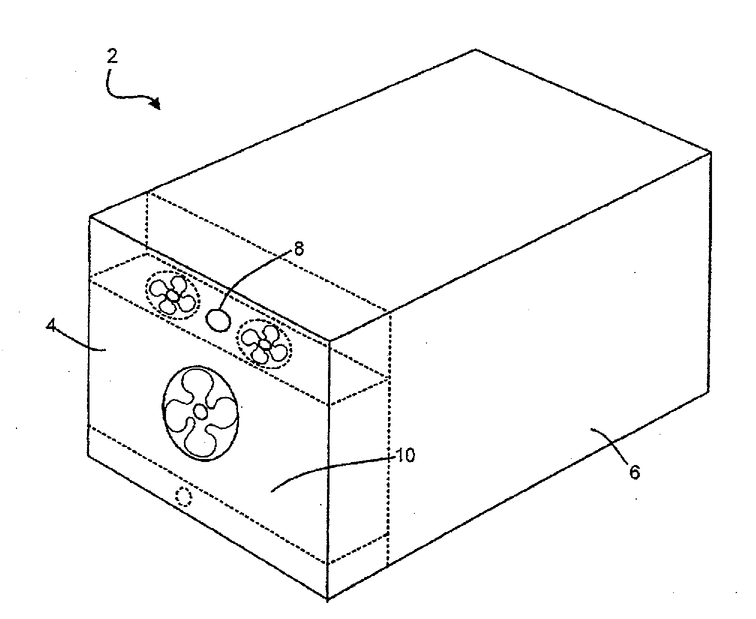
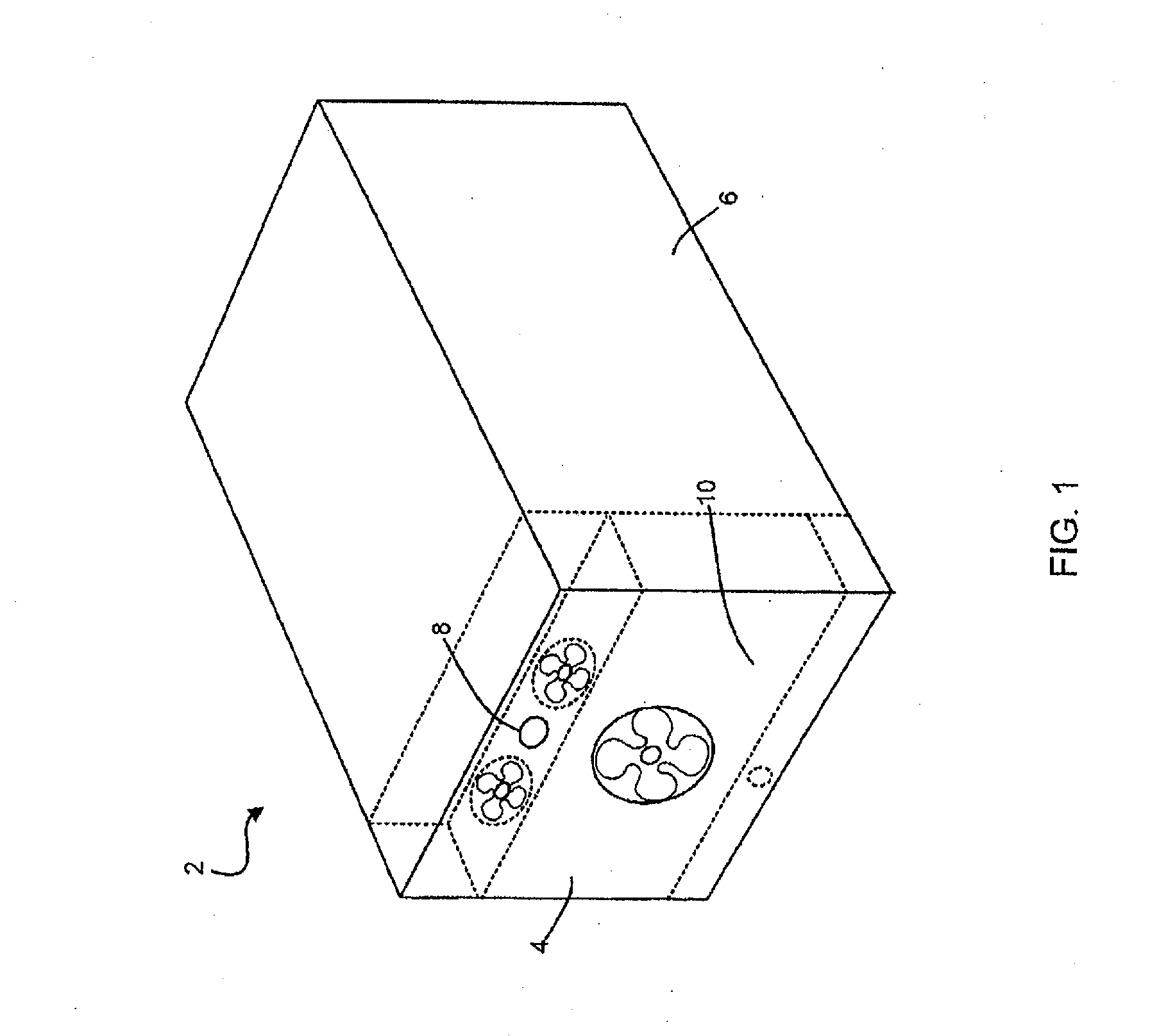
[0017]Referring to FIG. 1, a refrigerant vapor compression system 2 may include a transport refrigeration unit 4 coupled to an enclosed space within a container 6. The container 6 may be a temperature controlled environment, such as a cargo box of a refrigerated transport truck, trailer or container, or a display case, merchandiser, freezer cabinet, cold room or other perishable / frozen product storage area in a commercial establishment, or a climate controlled comfort zone within a residence, office building, hospital, school, restaurant or other facility. In the disclosed example, the refrigerant vapor compression system 2 is of the type utilized on refrigerated transport truck. As shown in FIG. 1, the transport refrigeration unit 4 is configured to maintain a programmed thermal environment within the container 6.

[0018]In FIG. 1, the transport refrigeration unit 4 is mounted at one end of the container 6. However, the transport refrigeration unit 4 may also be mounted to one or mor...


PUM


Abstract

Embodiments of apparatus, transport refrigeration units, and methods for operating the same can control defrost operations for a refrigerant vapor compression system. Embodiments can provide control for transitioning a refrigerant vapor compression system into and out of a defrost mode.

Description

CROSS-REFERENCE TO RELATED APPLICATION[0001]This application claims priority to U.S. Provisional Patent Application Ser. No. 61 / 311,612 entitled “Defrost Operations and Apparatus for a Transport Refrigeration System” filed on Mar. 8, 2010, the content of which is incorporated herein by reference in its entirety.FIELD OF THE INVENTION[0002]This disclosure relates generally to refrigeration systems and, more specifically, to methods and apparatus for controlling a refrigerant vapor compression system.BACKGROUND OF THE INVENTION[0003]Conventional vapor compression systems typically include a compressor, a heat rejection heat exchanger, a heat absorption heat exchanger, and an expansion device disposed upstream of the heat absorption heat exchanger. Some systems further include a second expansion device downstream of the heat rejection heat exchanger, such as a suction modulation valve. These basic system components are interconnected by working fluid lines in a closed circuit.[0004]Dep...

Claims


Application Information

Patent Timeline
IPC IPC(8): F25D21/06
CPCF25B1/053Y02B30/741F25B9/008F25B41/043F25B49/02F25B2309/061F25B2341/0662F25B2400/13F25B2400/23F25B2600/0253F25B2600/2509F25B2600/2513F25B2700/1931F25B2700/1933F25B2700/197F25B2700/2106F25B2700/21151F25B2700/21152F25B2700/21161F25B2700/21175F25D21/08F25B1/10F25B31/008Y02B30/70F25B41/22F25B41/39
Inventor LIU, LUCY YIDURAISAMY, SURESHHOFSDAL, GILBERT B.
Owner CARRIER CORP
Why Eureka
Eureka Blog
Learn More