Shift control method of automatic transmission

a technology of automatic transmission and shift control, which is applied in the direction of gearing control, coupling-brake combination, gearing elements, etc., can solve the problems of deteriorating shifting performance, no hydraulic clutch physically absorbing torque variations, and deteriorating shifting performance, so as to increase the marketability of the vehicle and enhance the shifting performance

Active Publication Date: 2012-12-20
HYUNDAI MOTOR CO LTD +1
View PDF3 Cites 7 Cited by
  • Summary
  • Abstract
  • Description
  • Claims
  • Application Information

AI Technical Summary

Benefits of technology

[0011]Various aspects of the present invention are directed to providing a shift control method of an automatic transmission in which gears are shifted by engaging and releasing frictional elements using hydraulic pressure, and which is configured such that shift shock is mitigated or prevented from occurring at a late stage of the shifting, thus enhancing the shifting performance, thereby increasing the marketability of the vehicle.

Problems solved by technology

That is, such a conventional torque converter itself absorbs a large proportion of the vibrations or shocks which occurs in a power transmission system due to variations in torque when shifting gears.
However, in a parallel hybrid system or the like in which an electric motor in place of a torque converter is coupled to an input shaft of a transmission by a rigid body, there is no hydraulic clutch which physically absorbs variations in torque which is induced when shifting gears.
Therefore, such variation in torque just causes shift shock, thus markedly deteriorating shifting performance.
In the case of the conventional system provided with the torque converter, slip operation of the torque converter absorbs the majority of such rapid variations in torque, but in the case of a system having no torque converter, rapid variations in torque at the late stage of the shifting process are responsible for deterioration of the shifting performance.
However, in the case of a system having no torque converter, such a shock is just transmitted to the power transmission system as shift shock, thus markedly deteriorating the shifting performance of the vehicle.

Method used


Image

  • Shift control method of automatic transmission
  • Shift control method of automatic transmission
  • Shift control method of automatic transmission

Examples


Embodiment Construction

[0025]Reference will now be made in detail to various embodiments of the present invention(s), examples of which are illustrated in the accompanying drawings and described below. While the invention(s) will be described in conjunction with exemplary embodiments, it will be understood that the present description is not intended to limit the invention(s) to those exemplary embodiments. On the contrary, the invention(s) is / are intended to cover not only the exemplary embodiments, but also various alternatives, modifications, equivalents and other embodiments, which may be included within the spirit and scope of the invention as defined by the appended claims.

[0026]Hereinafter, the present invention will be described in detail with reference to the attached drawings.

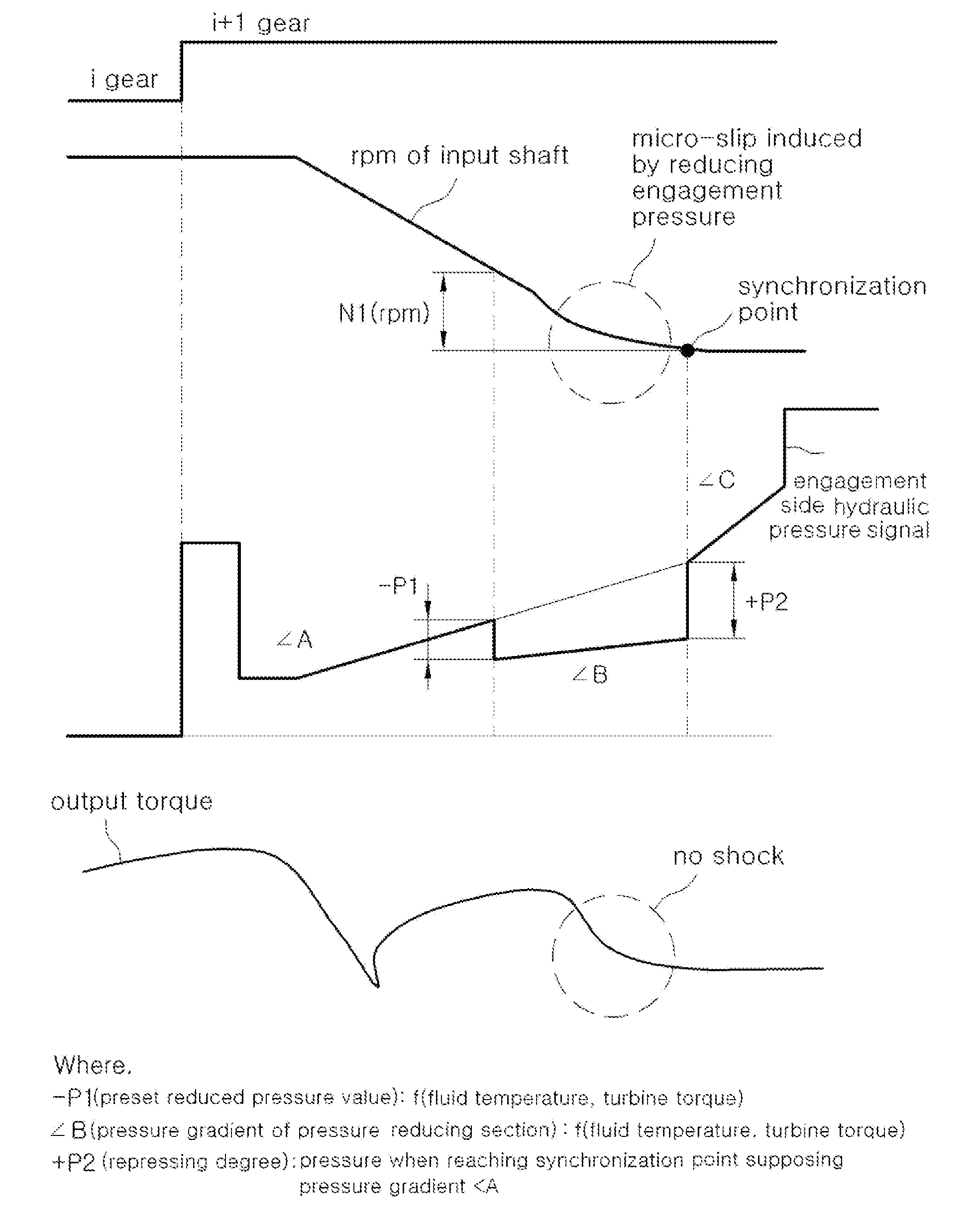
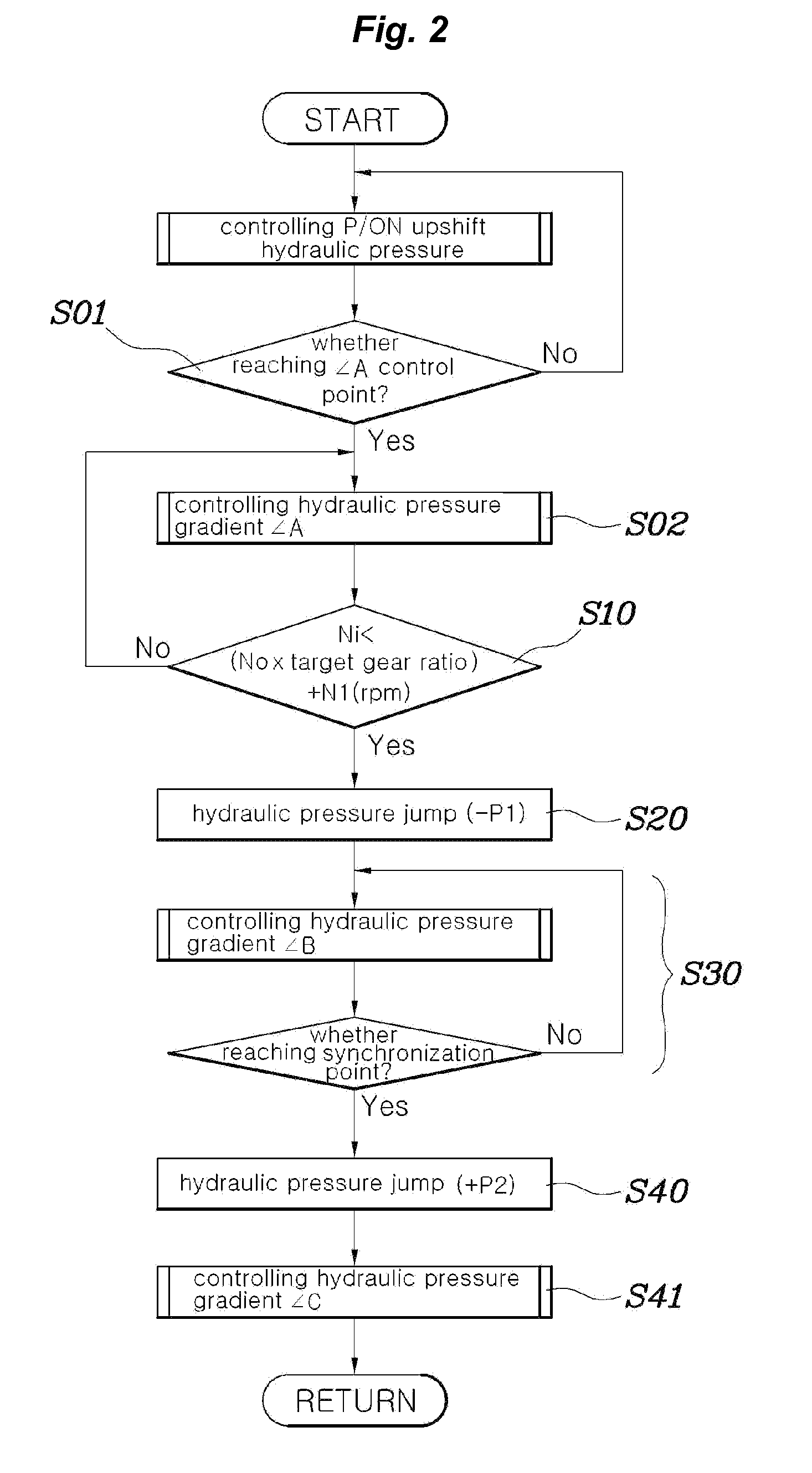
[0027]Referring to FIGS. 2 and 3, a shift control method of an automatic transmission according to an exemplary embodiment of the present invention includes a first step S10 of detecting an end point of an inertia section d...


PUM


Abstract

A shift control method of an automatic transmission may include detecting an end point of an inertia section during upshifting, momentarily reducing a hydraulic pressure applied to engagement side frictional elements at the detected end point of the inertia section, increasing the reduced hydraulic pressure with a predetermined gradient until reaching a synchronization point, and momentarily increasing the hydraulic pressure when the synchronization point may be reached.

Description

CROSS-REFERENCE TO RELATED APPLICATIONS[0001]The present application claims priority to Korean Patent Application No. 10-2011-0059546 filed on Jun. 20, 2011, the entire contents of which is incorporated herein for purposes by this reference.BACKGROUND OF THE INVENTION[0002]1. Field of the Invention[0003]The present invention relates generally to a shift control method of an automatic transmission and, more particularly, to a technique for mitigating shift shock when upshifting.[0004]2. Description of Related Art[0005]The ultimate goal of controlling an automatic transmission is embodying smooth shifting performance. In the conventional technique, hydraulic power transmission apparatuses, such as torque converters, have played an important role in ensuring such smooth shifting performance.[0006]That is, such a conventional torque converter itself absorbs a large proportion of the vibrations or shocks which occurs in a power transmission system due to variations in torque when shiftin...

Claims


Application Information

Patent Timeline
Patent Type & Authority Applications(United States)
IPC IPC(8): F16H61/06
CPCF16H2059/462F16H61/061F16H61/68F16H61/04F16H61/06F16H61/02F16H59/72
Inventor JEON, BYEONG WOOK
Owner HYUNDAI MOTOR CO LTD
Why Eureka
Try Eureka