
Quick-connect coupling

Active Publication Date: 2012-12-20
VON ARX AG
View PDF3 Cites 24 Cited by
  • Summary
  • Abstract
  • Description
  • Claims
  • Application Information

AI Technical Summary

Benefits of technology

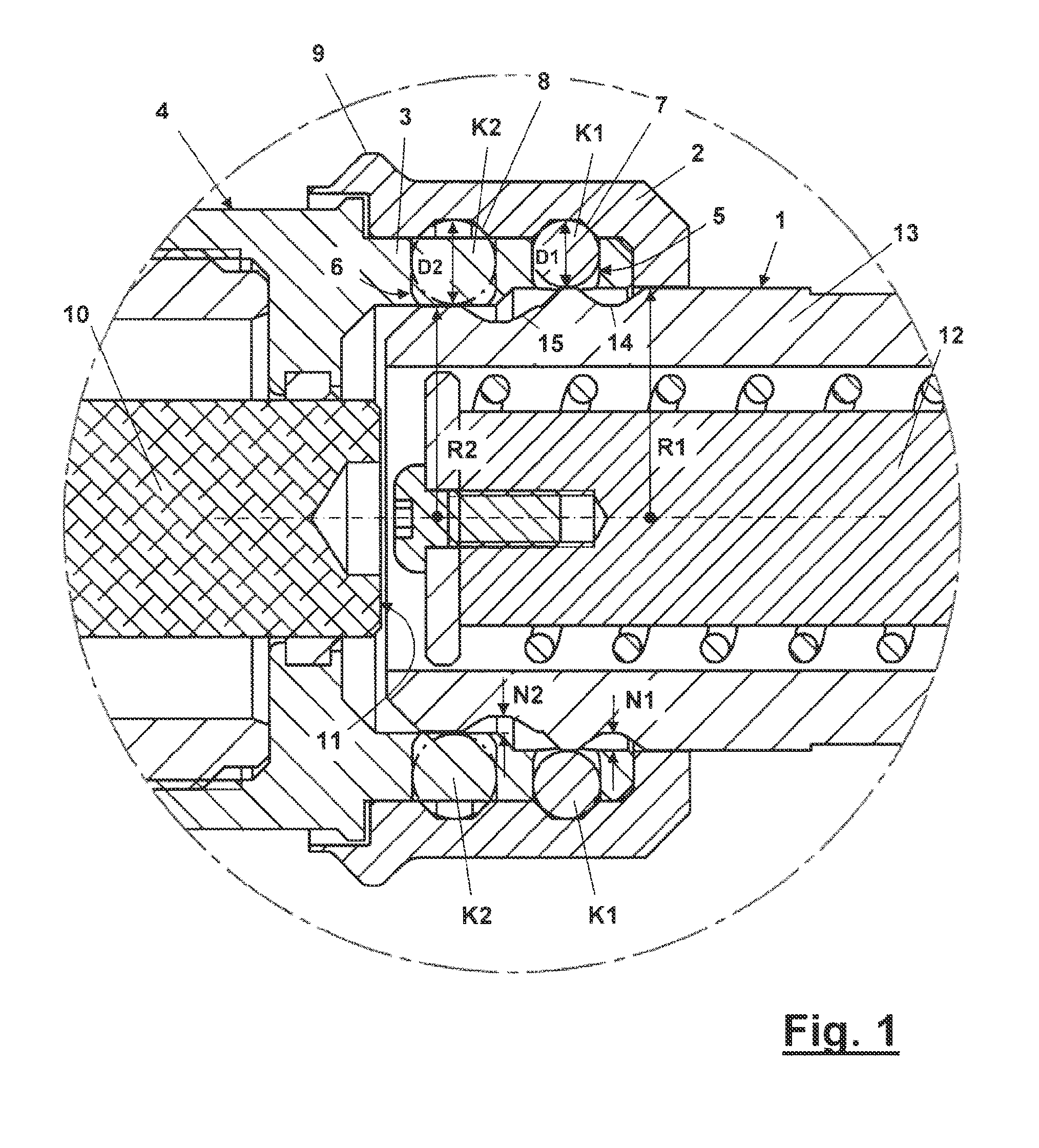
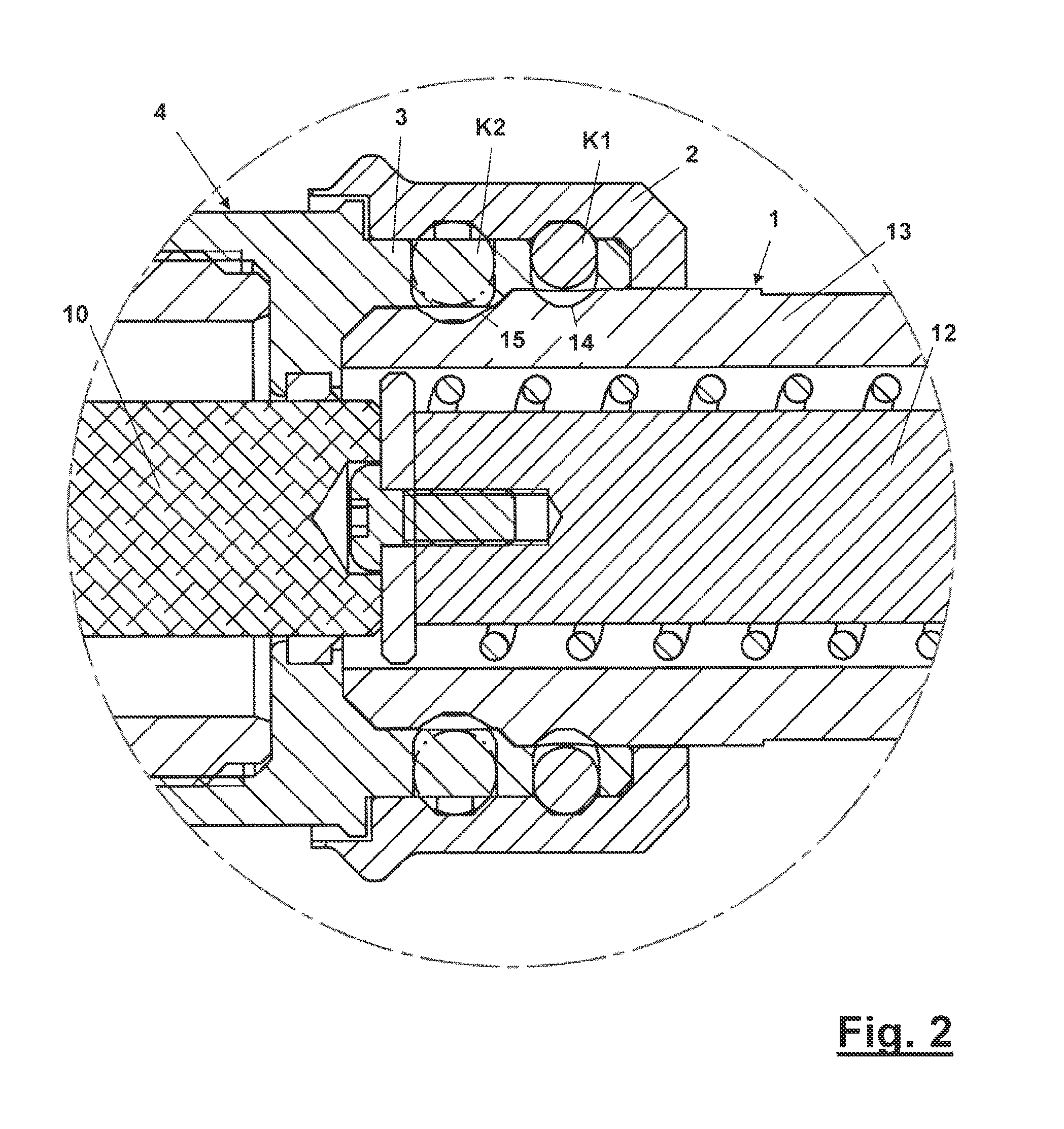
[0008]It is anobject of the present disclosure, therefore, to indicate a quick-connect coupling with loading capacity to connect an exchangeable head to a pressing device, wherein the quick-connect coupling is based on the known construction principle with movable locking bodies in the form of balls, which engage in corresponding grooves in an exchangeable head in the coupled state. This quick-connect coupling should endure high longitudinal traction forces on a sustained basis and, if possible, without wear and guarantee a high degree of safety.
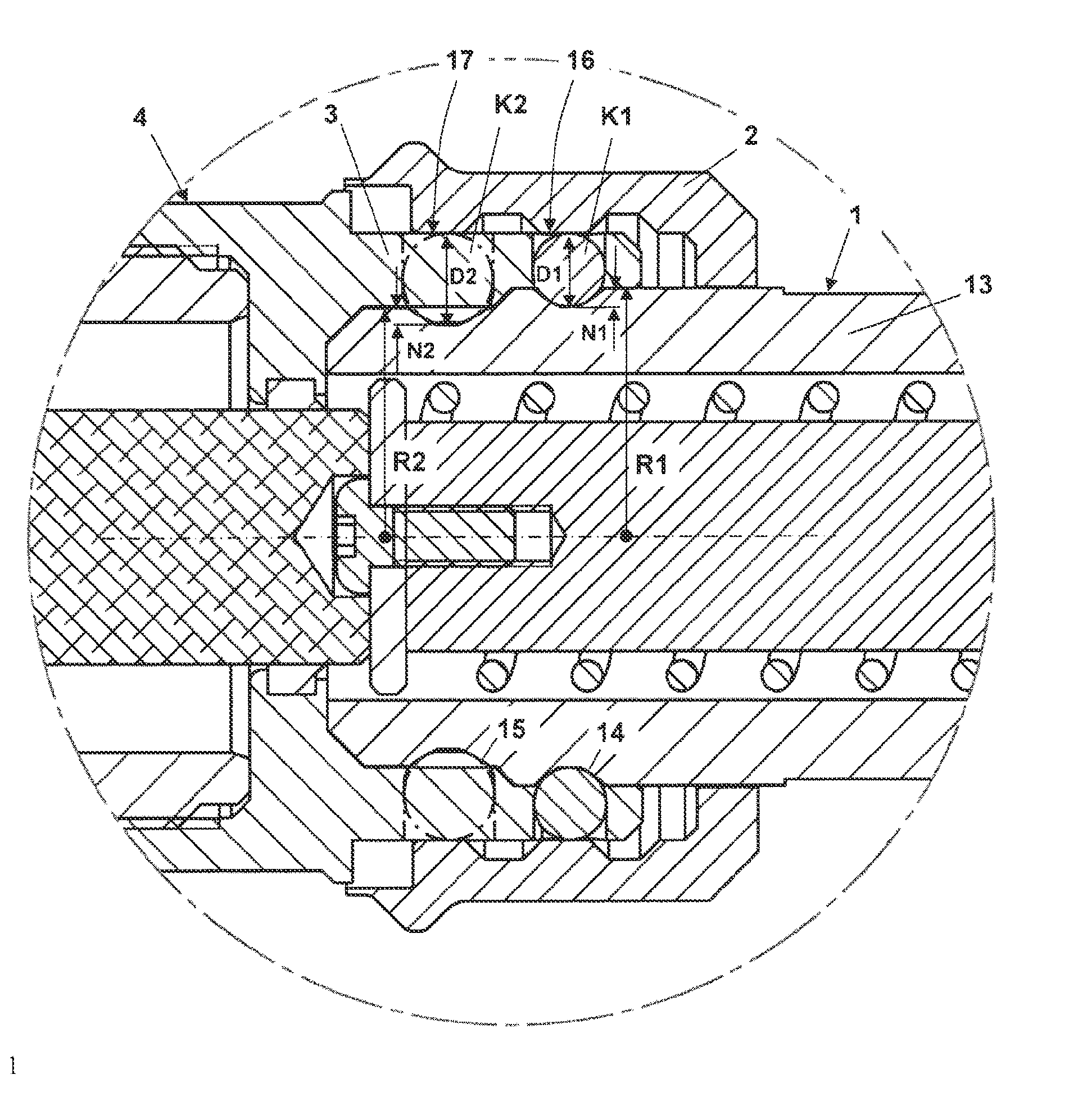
[0015]By using a further peripheral groove and with the associated use of a larger number of locking bodies (balls), as well as with balls of different sizes, it is possible to achieve the transmission of smaller forces per locking body (ball), or else the transmission of greater forces. The dimensions of the quick-connect coupling, i.e. particularly the dimensions of the balls K1, K2 and the groove depth N2, mean that if the exchangeable head is not completely inserted into the ball-holding part on the pressing device, a fixed connection cannot be made (in other words, a connection in which power is only transmitted across a single peripheral groove and the locking bodies engaging with it). Non-lockability in the event of incorrect assembly is notably important, because this is exactly what must be completely and reliably prevented, due to the associated risks (breakage of the quick-connect coupling when there is a build-up of pressure). The present disclosure has the added advantage that an embodiment functions purely mechanically and does not require electronic monitoring.
[0016]It has also emerged that with two peripheral grooves and a total of at least 12 balls—and of course using tool steels that are sufficiently hard and tough to avoid lasting deformation—the specified longitudinal forces in the region of 60 kN can be reliably transmitted.
[0017]Also advantageous is an angularly offset arrangement of the balls K1 in the peripheral groove compared with the balls K2 in the further peripheral groove. The forces can thereby be more effectively distributed over the entire cross-section.
[0018]A further advantage is also that an arrangement of the embodiment facilitates the unlimited twistability of the exchangeable head in relation to the pressing device.
[0019]A further measure that ensures that the quick-connect coupling is able to withstand high longitudinal traction forces on a sustained basis and with as little wear as possible, involves the peripheral grooves each being provided with a base surface and side faces, namely in such a way that the balls K1 and K2 have a point contact with the base surface and the side faces in the connected state and that the point contact with the side face is made roughly in the region of the half groove depth N1, N2. This means that the locating point of the balls is moved from the entry edge of the peripheral grooves sensitive to deformation towards the entry centre of the peripheral grooves, which significantly increases wear resistance.

Problems solved by technology

However, a particular problem affecting pressing devices with exchangeable heads is the longitudinal forces being transmitted, in other words, the compressive forces produced by the pressing devices, because the coupling mechanism by which the exchangeable head is attached to the pressing device naturally has to withstand these forces and the corresponding safety requirements are relatively high.
Although longitudinal forces are naturally also active here, these are compressive forces (seen in relation to the machine tool / tool connection), so that there is no risk of the quick-connect coupling being released under load by the longitudinal forces and thereby representing a safety risk.
Because this is an application in which pressurised fluids are conducted through connectable lines, although there is a certain safety risk, because evidently no applications involving very high fluid pressures are envisaged, additional measures do not seem necessary.

Method used


Image

  • Quick-connect coupling
  • Quick-connect coupling
  • Quick-connect coupling

Examples


Embodiment Construction

[0025]As required, detailed embodiments are disclosed herein; however, it is to be understood that the disclosed embodiments are merely examples and that the systems and methods described below can be embodied in various forms. Therefore, specific structural and functional details disclosed herein are not to be interpreted as limiting, but merely as a basis for the claims and as a representative basis for teaching one skilled in the art to variously employ the present subject matter in virtually any appropriately detailed structure and function. Further, the terms and phrases used herein are not intended to be limiting, but rather, to provide an understandable description of the concepts.

[0026]The terms “a” or “an”, as used herein, are defined as one or more than one. The term plurality, as used herein, is defined as two or more than two. The term another, as used herein, is defined as at least a second or more. The terms “including” and “having,” as used herein, are defined as comp...


PUM


Abstract

A quick-connect coupling for connecting an exchangeable head to a pressing device has balls K1 with a diameter D1, which are radially movably disposed in a ball-holding part on the pressing device. Balls K1 being held radially fixed in a groove on the head with a depth N1 by a locking ring in the connected state. The head has a further peripheral groove with a depth N2. The further groove is designed to hold part of further balls K2 with a diameter D2, wherein the balls K2 are likewise disposed in a radially movable manner in the ball-holding part and wherein the diameter D2 is greater than the diameter D1. The diameter D1 is the same or smaller than the difference between the diameter D2 and the groove depth N2.

Description

CROSS REFERENCE TO RELATED APPLICATIONS[0001]This application claims priority to Swiss Patent Application No. CH-01006 / 11 filed Jun. 16, 2011 the contents of which are incorporated herein by reference.FIELD OF THE INVENTION[0002]The invention relates to a quick-connect coupling for connecting an exchangeable head to a pressing device.BACKGROUND OF THE INVENTION[0003]Pressing devices are used for various purposes, such as, for example, pressing cable shoes onto electrical cables, but also for cutting cables or punching holes into sheet metal constructions. In order to perform these different applications on one machine, an exchangeable head system is required. To simplify matters, the different mountable heads are referred to in the following as exchangeable heads. Using the same pressing device with different exchangeable heads, it is quick and easy to change over to different applications where necessary.[0004]However, a particular problem affecting pressing devices with exchangeab...

Claims


Application Information

Patent Timeline
IPC IPC(8): F16L37/23
CPCB30B15/026B23B31/1071B23B31/263B23B2260/022Y10T279/17145Y10T279/17196Y10T279/17752Y10T279/17811
Inventor SCHWEIZER, BEATMORITZ, MARTIN
Owner VON ARX AG
Learn More