Method for controlling a converter

a three-phase converter and control method technology, applied in the direction of control systems, power conversion systems, electrical equipment, etc., can solve the problems of high load on individual switching elements, achieve the effect of reducing the degree of efficiency of the polyphase system, reducing the stress limit value of an individual switching element, and reducing the switching loss

Active Publication Date: 2012-12-20
DIEHL AKO STIFTUNG
View PDF12 Cites 10 Cited by
  • Summary
  • Abstract
  • Description
  • Claims
  • Application Information

AI Technical Summary

Benefits of technology

[0051]In a further preferred refinement, the converter is operated with the modulation method of single-phase switching when the polyphase system is operated with output voltage above a minimum voltage value. Single-phase clocking is selected when, for example, the maximum fundamental voltage is intended to be output, in order to further reduce the switching losses and in order to make the full voltage from the voltage intermediate circuit available for the polyphase system.
[0052]The minimum voltage value is preferably selected to be between 60% and 70% of the possible voltage adjustment range of the converter. Above this minimum voltage value, it has been found that a changeover from two-phase switching to single-phase switching exhibits advantages in respect of the maximum stress loading on a switching element of the converter. The changeover is implemented by suitable open-loop and closed-loop control methods. In this case, single-phase switching is expediently favored since measures are taken so that, above the specified minimum voltage value, the voltages which are output by

Problems solved by technology

A modulation method which clamps a half-bridge on one side in this respect for certain time periods therefore leads

Method used


Image

  • Method for controlling a converter
  • Method for controlling a converter
  • Method for controlling a converter

Examples


Embodiment Construction

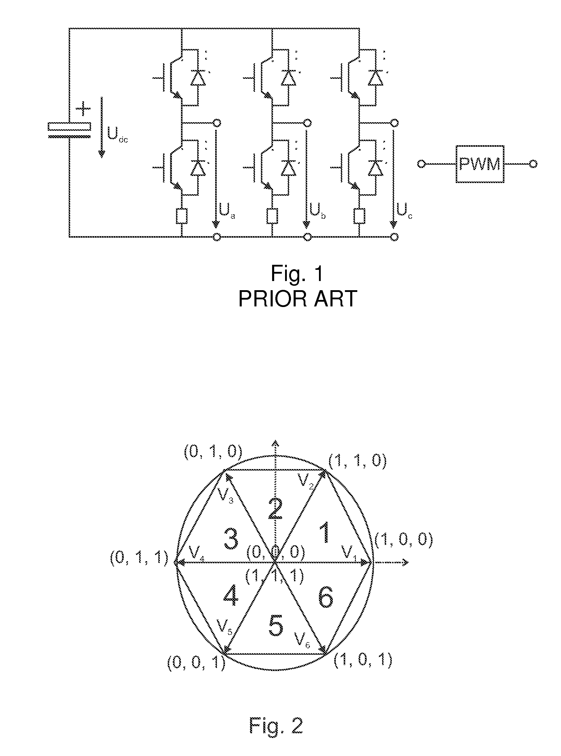
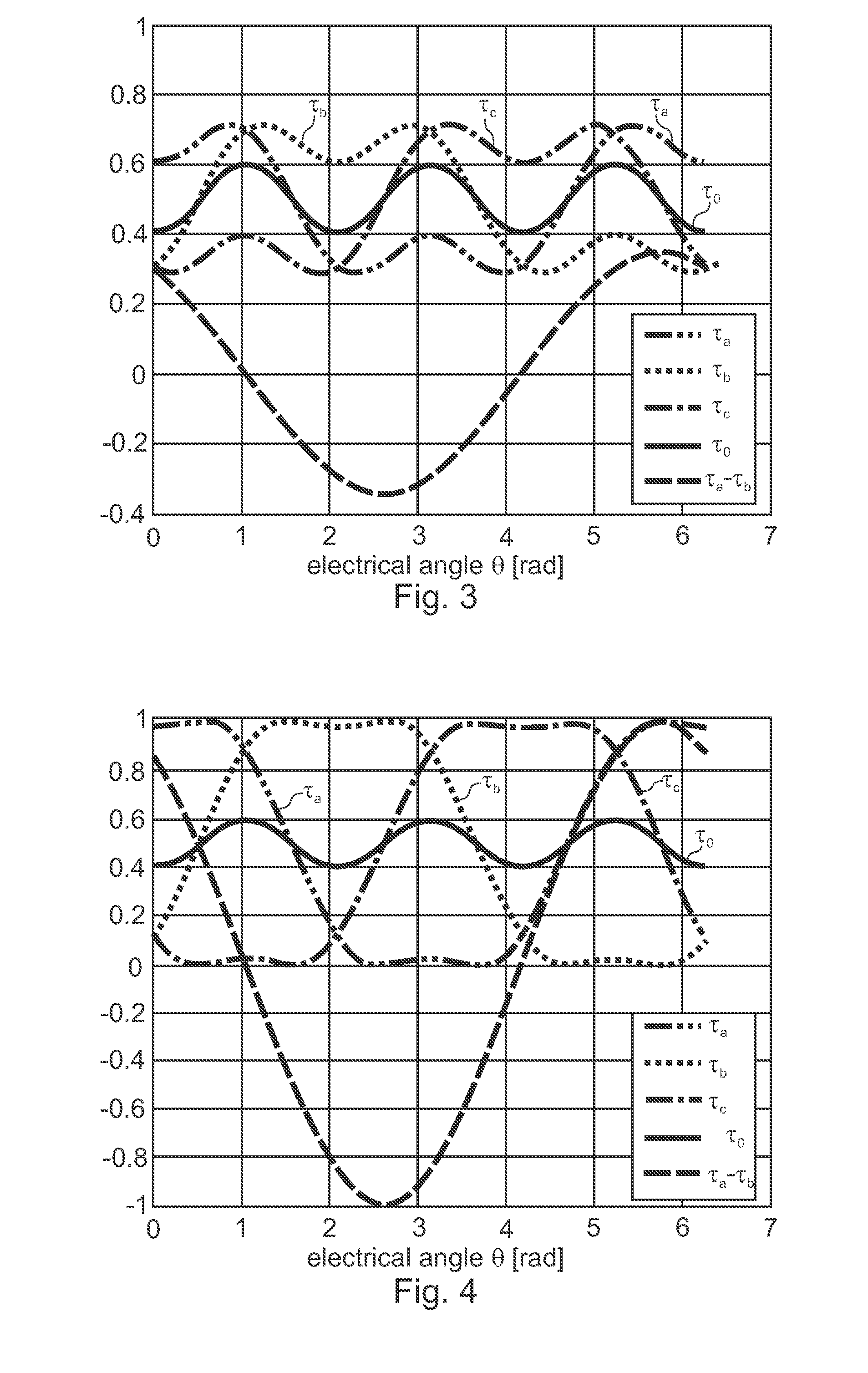
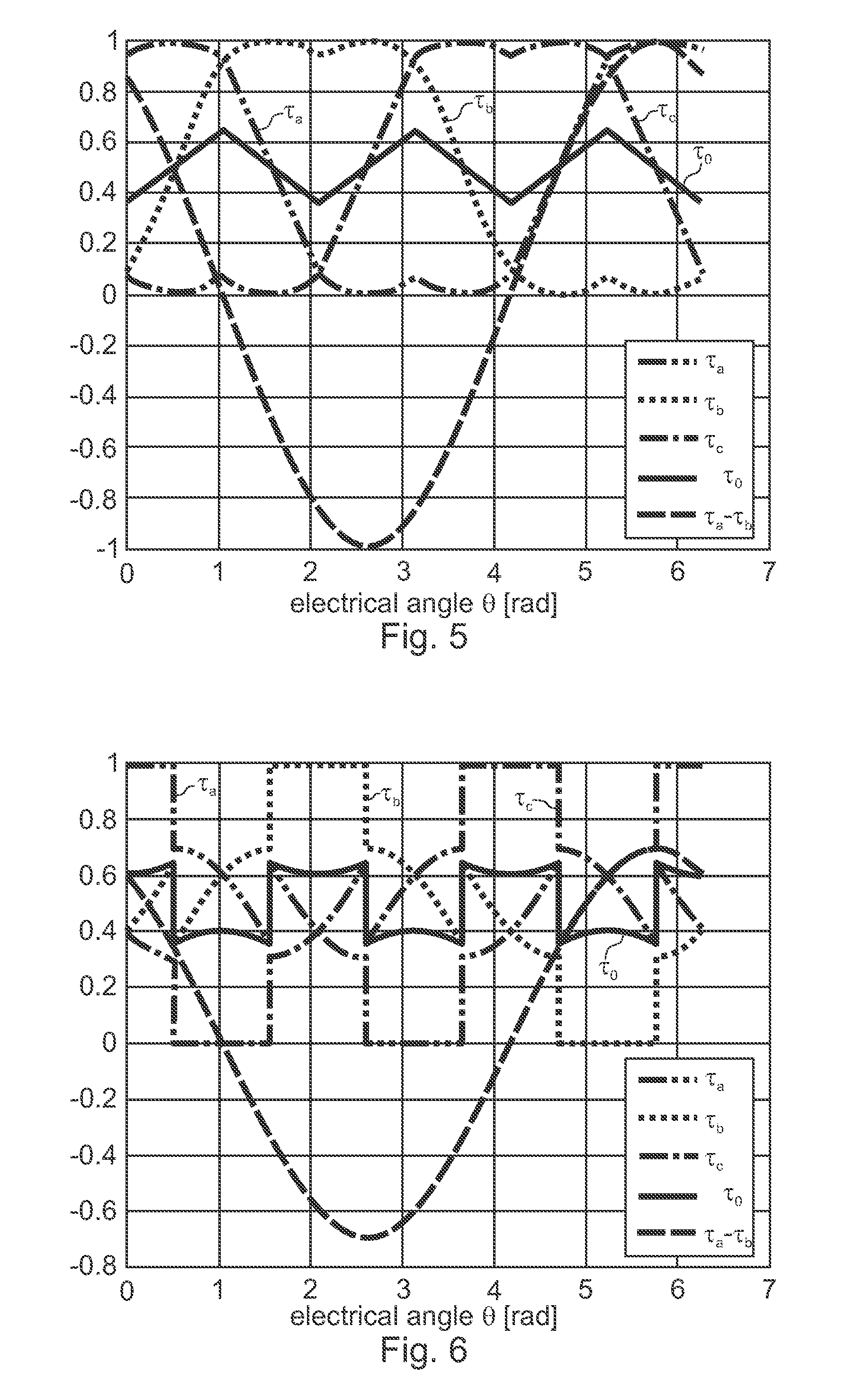
[0072]FIGS. 1-2 and 3-8 have already been explained in detail in connection with the description of the invention. Accordingly, reference is made to the relevant passages of the description.

[0073]FIG. 9 shows a profile, which is measured by an oscilloscope, of an output voltage of the phase of a three-phase converter (lower profile) with the corresponding switching cycles of the associated half-bridge (upper profile). In this case, the converter is operated with a modulation method of two-phase switching according to the “120° bus-clamped” method. The associated half-bridge is accordingly permanently clamped to the lower intermediate circuit potential for 120° in each case. The switching elements of the half-bridge are not clocked in this region, as clearly shown in the upper profile. The voltage amplitude is selected in such a way that it moves at the maximum in the vicinity of the voltage limit. In this respect, overmodulation occurs sporadically, this being shown in the upper pro...


PUM


Abstract

A method controls a three-phase converter with a voltage intermediate circuit by pulse-width modulation for supplying a polyphase system, in particular a three-phase machine. The converter is operated with at least two different modulation methods which are selected from among the group of modulation methods which includes single-phase switching, two-phase switching and three-phase switching, and for chageovers to be made between the at least two different modulation methods depending on the operating state of the polyphase system.

Description

CROSS -REFERENCE TO RELATED APPLICATION[0001]This application claims the priority, under 35 U.S.C. §110, of German applications DE 10 2011 104 742,9, filed Jun. 17, 2011, DE 10 2011 116 615.0, filed Oct. 20, 2011 and DE 10 2011 120 333.1, filed Dec. 6, 2011; the prior applications are herewith incorporated by reference in their entireties,BACKGROUND OF THE INVENTION[0002]1. Field of the Invention[0003]The invention relates t(c) a method for controlling a three-phase converter with a voltage intermediate circuit by use of pulse-width modulation for supplying a polyphase system, in particular a three-phase alternating-current system. The polyphase system may likewise be a machine which is operated as a motor or as a generator (three-phase machine), such as a three-phase power supply system. In particular, the invention also relates to a three-phase motor of a domestic washing machine or of a drive for art automobile. The three-phase motor can be operated in the field-weakening mode or...

Claims


Application Information

Patent Timeline
IPC IPC(8): H02M7/48
CPCH02P27/085H02M7/53875H02M2007/53876H02M7/53876
Inventor WEINMANN, MARTINZEH, STEFANOLARESCU, NICOLA-VALERIU
Owner DIEHL AKO STIFTUNG
Why Eureka
Try Eureka