
Convertible and Compact Refrigeration System

a refrigeration system and compact technology, applied in the field of refrigeration systems, can solve the problems of inability to use one motor to turn a single traditional centrifugal fan, increased noise and motor vibration, and inability to accept noise and vibration

Active Publication Date: 2012-12-20
THE MONTAGUE CO
View PDF13 Cites 0 Cited by
  • Summary
  • Abstract
  • Description
  • Claims
  • Application Information

AI Technical Summary

Benefits of technology

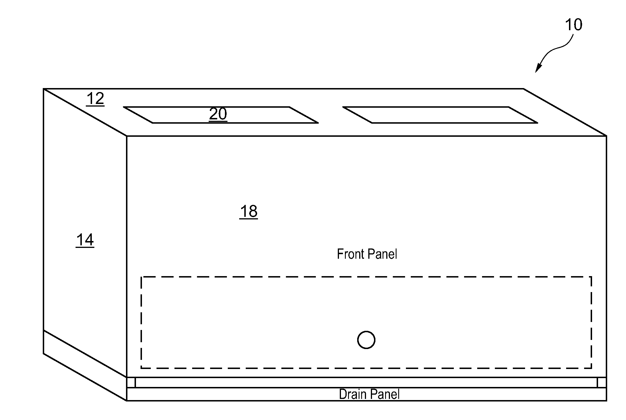
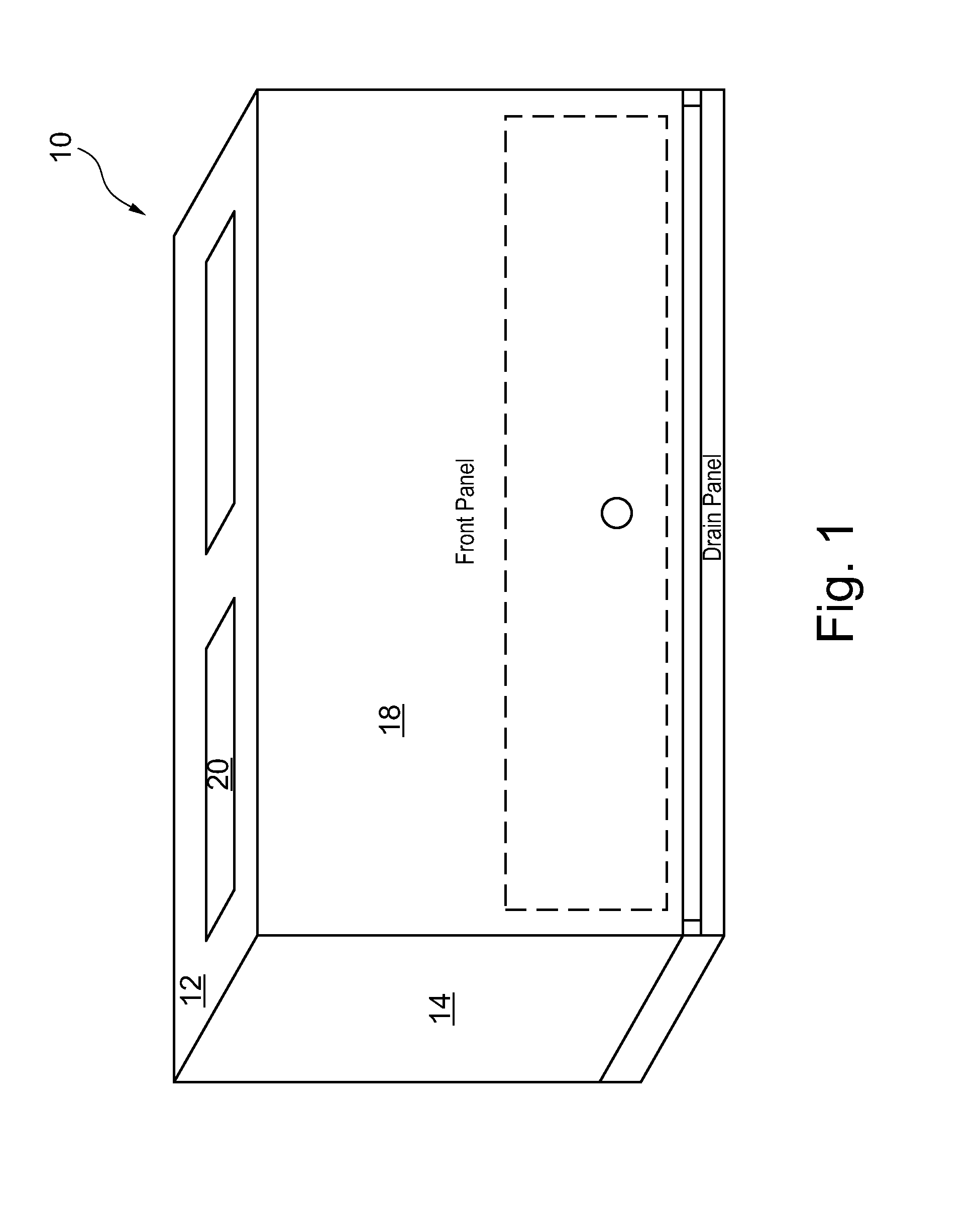
[0007]The present invention overcomes shortfalls in the related art by presenting an unobvious and unique combination and configuration of coils, blowers, a blower motor and other components to provide a compact unit with means of easily redirecting cooled air flow to fit various applications.
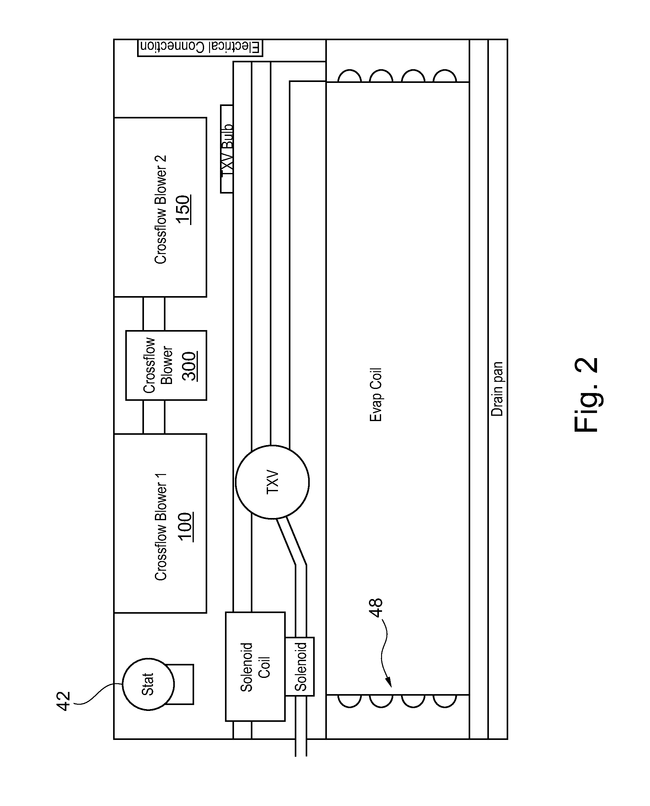
[0008]One of the main advantages of this invention is the creation of a twin cross flow blower system comprising two air blower turbines placed on either side of a unique cross flow motor. The twin blower turbines are sometimes referred to herein as a “cross flow blower” and are sometimes named “cross flow blower 1” and cross flow blower 2. The placement of a cross flow motor between the two disclosed cross flow blowers has achieved unexpectedly favorable results in efficiently moving cooled air to a targeted area.
[0010]The disclosed configuration of a center cross flow motor flanked by two cross flow blowers placed over a compact coil system provides clear advantages over the related art in terms of weight and size.
[0013]The second embodiment overcomes shortfalls in the art by presenting a new fan and motor unit having artful fastening clips allowing the fan and motor unit to efficiently attached either of two positions within in the motor housing. The motor housing includes a back plate, fastener voids, two sets of discharge vents and other features not found in the prior art.

Problems solved by technology

Unfortunately, the system disclosed by Haasis leads to added noise and motor vibration due to the use of springy metal strips to secure the sub-unit to the housing.
When a fan motor needs replacement, the typical service technician will not have the necessary sealants, which results in a newly installed motor causing unacceptable noise and vibration.
Another shortfall in the Haasis system is the inefficiency of using one motor to turn a single traditional centrifugal fan.
The added load to the motor from the second cooling fan often creates more heat than what is removed by the second fan.
Furthermore, the coil configuration of the Haasis system fails to adapt to varying food storage containers or other applications with untraditional dimensions and access problems.
Moreover, the overall configuration of the Haasis system leads to a heavy cooling system making installation difficult in overhead locations.

Method used


Image

  • Convertible and Compact Refrigeration System
  • Convertible and Compact Refrigeration System
  • Convertible and Compact Refrigeration System

Examples


first embodiment

[0097]FIGS. 11 to 16 depict various parts and aspects of a

second embodiment

[0098]FIG. 17 depicts a second embodiment comprising a top plate 510, a condensation pan 500, a motor 515, a liquid line u bend 520, a TXV valve 525 one or more cross-flow blower wheels 530, a coated evaporator coil 535 and a sensing bulb 540.

[0099]FIG. 18 depicts a lower housing 544, motor housing 551, the motor housing shown with a back plate 570, top plate 550 of motor housing and discharge vents 555 for top discharge. FIG. 18 also depicts a front discharge plate cover 545 having discharge vents 546 for side discharge. A digital control stat 560 is shown fastened to the front discharge plate cover 545.

[0100]FIG. 19 depicts a second embodiment in general 501. In the foreground a top plate 550 of the motor housing is shown with discharge vents 555 for top discharge of cooled air. The top plate 550 of the motor housing also has a plurality of fastener voids sometimes used to secure fastening clips on the fan and motor unit. In the background, FIG. 19 depicts a front discharge plate ...


PUM


Abstract

A refrigeration system comprises a fan and motor unit 575 having a plurality of cross-flow blower wheels 530 or air blower turbines place upon either side of a motor or unique cross flow motor. The fan and motor unit 575 may be attached to either a top plate 550 to create a side discharge or to a back plate 570 to create a top discharge. The top plate 550 comprises a plurality of top discharge vents and a front discharge plate cover 545 comprises a plurality of side discharge vents 546. A technician in the field may configure a disclosed refrigeration system either a side or top discharge by rotating the position of the fan and motor unit.

Description

CROSS-REFERENCE TO RELATED APPLICATIONS[0001]This is a Continuation in Part utility application based upon U.S. patent application Ser. No. 13 / 284,862 filed on Oct. 28, 2011 which is a non-provisional application based upon provisional application 61 / 407,572,512 filed on Oct. 28, 2010. These two related applications are incorporated herein by reference and made a part of this application. If any conflict arises between the disclosure of the invention in this utility application and that in the related applications, the disclosure in this utility application shall govern. Moreover, the inventor(s) incorporate herein by reference any and all patents, patent applications, and other documents hard copy or electronic, cited or referred to in this application or the two related applications.BACKGROUND OF THE INVENTION[0002](1) Field of the Invention[0003]The invention generally relates to refrigeration systems. More particularly, the invention relates to means and methods of producing a c...

Claims


Application Information

Patent Timeline
Patent Type & Authority Applications(United States)
IPC IPC(8): F04B39/06
CPCF25D17/067F25D2317/0683
Inventor DELGADILLO, HECTOR
Owner THE MONTAGUE CO
Learn More