Harmonic Rejection Mixer Architecture with Reduced Sensitivity to Gain and Phase Mismatches

a mixer and harmonic rejection technology, applied in the field of radio frequency receivers, can solve problems such as phase offset and duty cycle errors, phase and duty cycle mismatches, and limit the ultimate rejection achievable,

Active Publication Date: 2012-12-20
MAXLINEAR INC
View PDF3 Cites 41 Cited by
  • Summary
  • Abstract
  • Description
  • Claims
  • Application Information

AI Technical Summary

Benefits of technology

[0009]Embodiments of the present invention provide devices, systems, and methods for minimizing phase and duty cycle errors using a mixer that includes two switching stages. The switches in the first switching stage switch at a higher rate of N times the LO frequency, where N is an integer. The second switching stage includes N switches each of which is controlled by one of the N phases of the non-overlapping LO phases. The N phases of the LO of the second switching stage are aligned to the N*LO signal. Accordingly, the RF signal sampled at the output of each switch of the second switching stage is dependent only on the N*LO switches (symbol * represents multiplication operation). The other switches simply guide the sample to the appropriate output.

Problems solved by technology

This is a major problem in broad-band systems such as TV tuners or cable-systems, where the input signal range is wide-band.
In conventional reject mixers each sample of the received RF signal is defined by a separate switch and is hence susceptible to phase and duty cycle mismatches in the switches or the LO path.
Phase and gain errors through the different taps limit the ultimate rejection achievable from the topology.
Imperfections in the LO generation and mixing blocks result in a phase offset and duty cycle error.
Phase errors result in imperfect cancellation of harmonics at the summing node.
Duty cycle errors result in amplitude mismatch that also limits the harmonic rejection.
Minimizing phase and duty cycle errors without taking care of gain errors or vice versa limits the improvement in harmonic rejection that can be achieved.

Method used


Image

  • Harmonic Rejection Mixer Architecture with Reduced Sensitivity to Gain and Phase Mismatches
  • Harmonic Rejection Mixer Architecture with Reduced Sensitivity to Gain and Phase Mismatches
  • Harmonic Rejection Mixer Architecture with Reduced Sensitivity to Gain and Phase Mismatches

Examples


Embodiment Construction

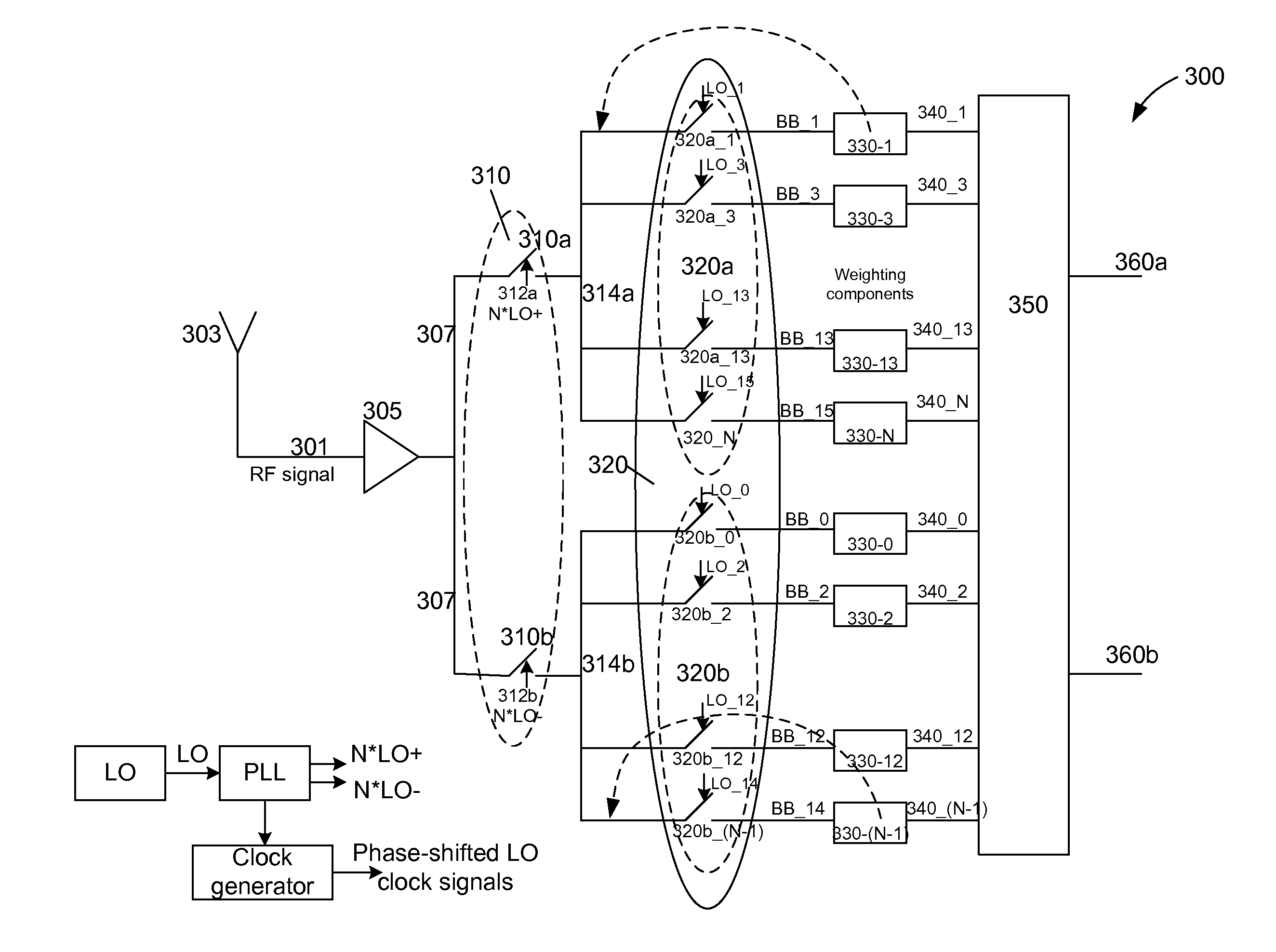
[0029]In accordance with embodiments of the present invention, both gain errors and phase and duty cycle errors are minimized to improve harmonic rejection beyond what can be achieved by minimizing gain and phase errors in isolation. A harmonic reject mixer in accordance with the present invention is implemented as a bank of mixers that include at least two switching stages (also referred to herein as mixing stages). Phase and duty cycle errors are minimized by using a mixer that includes at least 2 switching stages. The switches in the first switching stage switch at a higher rate of N times the LO frequency, where N is an integer. The second switching stage includes N switches each of which is controlled by one of the N phases of the non-overlapping LO phases. The N phases of the LO of the second switching stage are aligned to the N*LO signal. Accordingly, the RF signal sampled at the output of each switch of the second switching stage is dependent only on the N*LO switches (symbo...


PUM


Abstract

A harmonic rejection mixer includes a first scaling circuit for scaling an RF signal to generate a plurality of scaled RF signals, a first switching stage for sampling the scaled RF signals using a first plurality of switching signals, and a second mixing stage for mixing the sampled RF signals with a second plurality of switching signals to generate a plurality of frequency translated signals having different phases. A combiner adds the frequency translated signals together to generate a first plurality of baseband versions of the RF signal. A first amplifier stage processes the first plurality of baseband versions to generate a second plurality of baseband versions. The mixer further includes a second scaling circuit for scaling the second plurality of baseband versions and a second amplifier stage to generate an in-phase baseband signal and a quadrature baseband signal from the scaled second plurality of baseband versions.

Description

CROSS-REFERENCE TO RELATED APPLICATIONS[0001]The present application claims benefit under 35 USC 119(e) of U.S. provisional application No. 61 / 471,567, filed Apr. 4, 2011, entitled “Harmonic Rejection Mixer Architecture with Reduced Sensitivity to Gain and Phase Mismatches”, the content of which is incorporated herein by reference in its entirety.BACKGROUND OF THE INVENTION[0002]Embodiments of the present invention relate to the radio frequency (RF) receivers, and more particularly, to RF mixers.[0003]Mixers used in receivers today typically down-convert signals from various harmonics of a local oscillator frequency (LO) due to the square wave LO used in these implementations. Although the square wave LO results in better noise and linearity compared to a sinusoidal LO, the RF signal at harmonics of the square wave alias into the desired signal band at the output of the mixer. This is a major problem in broad-band systems such as TV tuners or cable-systems, where the input signal ra...

Claims


Application Information

Patent Timeline
Patent Type & Authority Applications(United States)
IPC IPC(8): H04B1/10
CPCH03D7/1466H03D7/166H03D2200/0086
Inventor PULLELA, RAJAPAIDI, VAMSIBHATIA, RAHUL
Owner MAXLINEAR INC
Why Eureka
Try Eureka