Dual Fuel Injection Compression Ignition Engine And Method Of Operating Same

a dual fuel injection and compression ignition technology, applied in the direction of electrical control, process and machine control, instruments, etc., can solve the problems of inability to control combustion characteristics, difficulty in achieving successful ignition of gaseous fuels, and relatively high hydrocarbon emissions

Active Publication Date: 2012-12-27
CATERPILLAR INC
View PDF11 Cites 83 Cited by
  • Summary
  • Abstract
  • Description
  • Claims
  • Application Information

AI Technical Summary

Benefits of technology

[0006]In another aspect, an electronically controlled compression ignition dual fuel engine includes a dual fuel injector positioned for direct injection into an engine cylinder. A source of gaseous fuel is fluidly connected to the dual fuel injector. A source of liquid fuel is also connected to the dual fuel injector. An electronic controller is in control communication with the dual fuel injector and includes an injection control algorithm configured to signal injection of a pilot ignition quantity of liquid fuel, to an engine cylinder from dual fuel injector in an engine cycle. In addition, the electronic controller is configured to signal an amount of gaseous fuel into the engine cylinder from the dual fuel injector in the engine cycle. The amount of gaseous fuel includes a pre-mix quantity and a post ignition quantity which are both greater than zero. Finally the electronic controller is configured to change a ratio of the pre-mix quantity of gaseous fuel to the post ignition quantity of gaseous fuel responsive to changing from a first engine speed and load to a second engine speed and load.

Problems solved by technology

However, gaseous fuels are well known for the difficulty in attaining successful ignition.
While this strategy may reduce NOx due to a cooler combustion, hydrocarbon emissions may be relatively high and there is no ability to control combustion characteristics, such as reaction rate, to accommodate different engine operating conditions.
While the reference claims that this strategy provides improved efficiencies over the counterpart gaseous fuel engines discussed previously, other emissions problems and power inefficiencies, especially at higher speeds and loads may be present.

Method used


Image

  • Dual Fuel Injection Compression Ignition Engine And Method Of Operating Same
  • Dual Fuel Injection Compression Ignition Engine And Method Of Operating Same
  • Dual Fuel Injection Compression Ignition Engine And Method Of Operating Same

Examples


Embodiment Construction

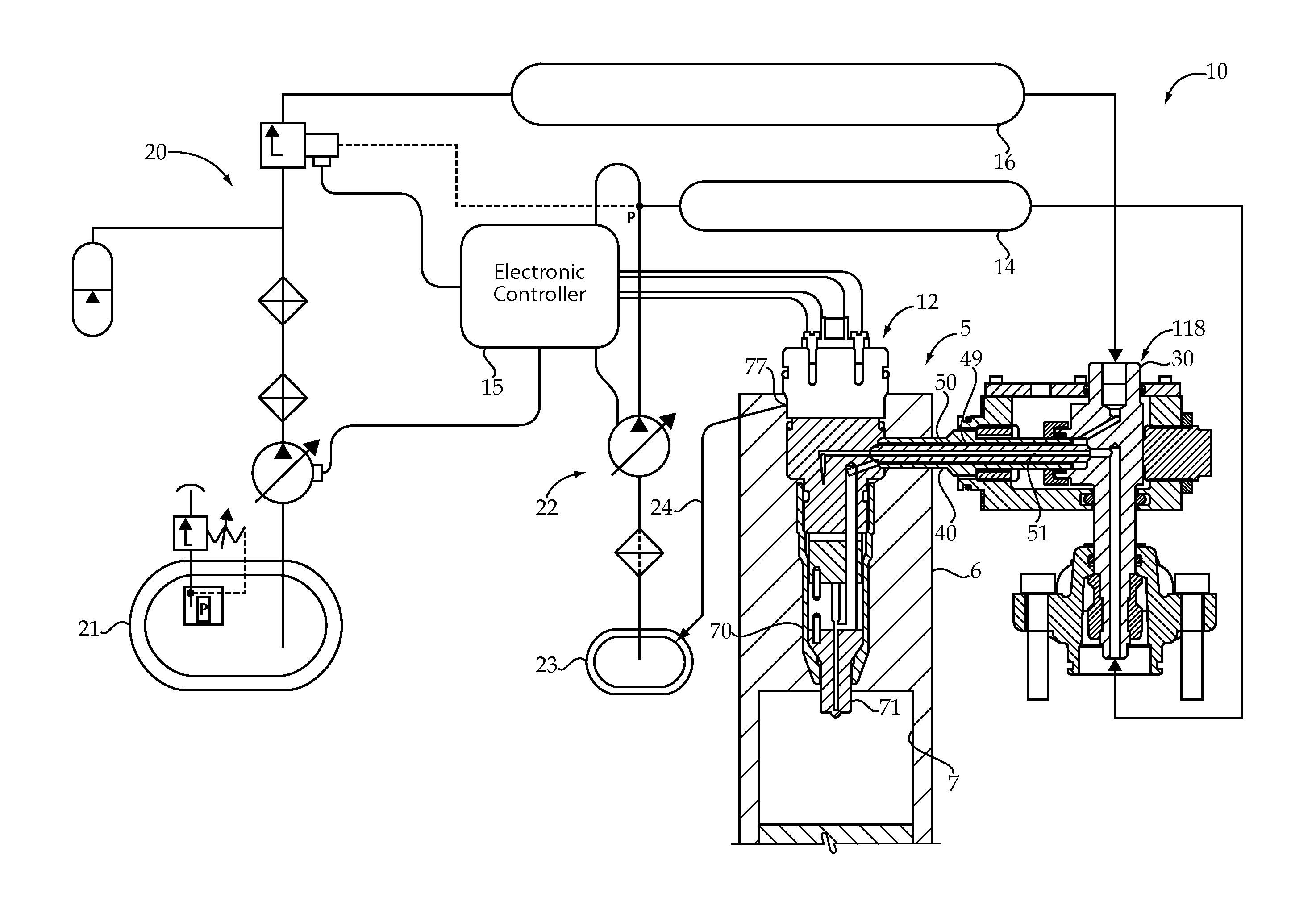
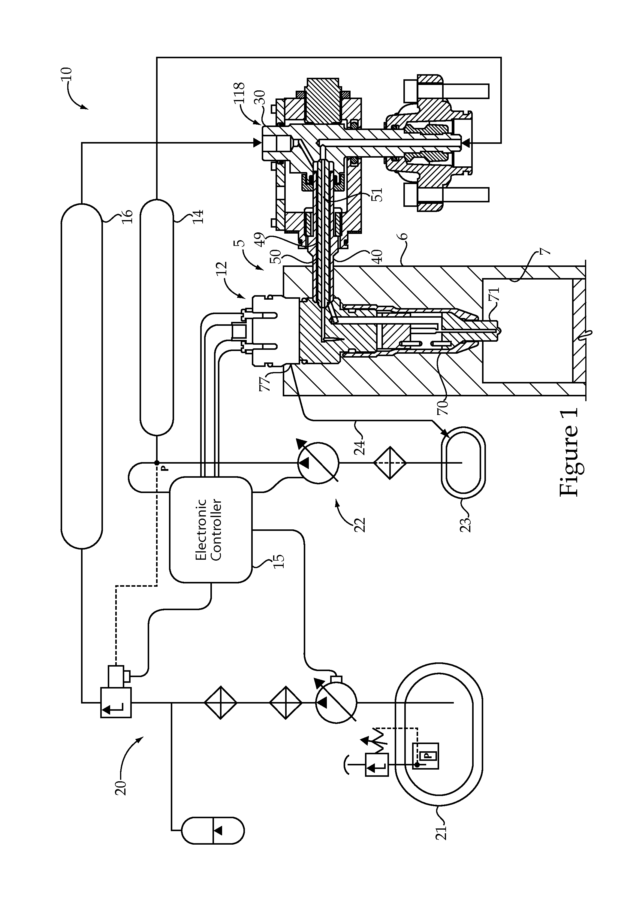
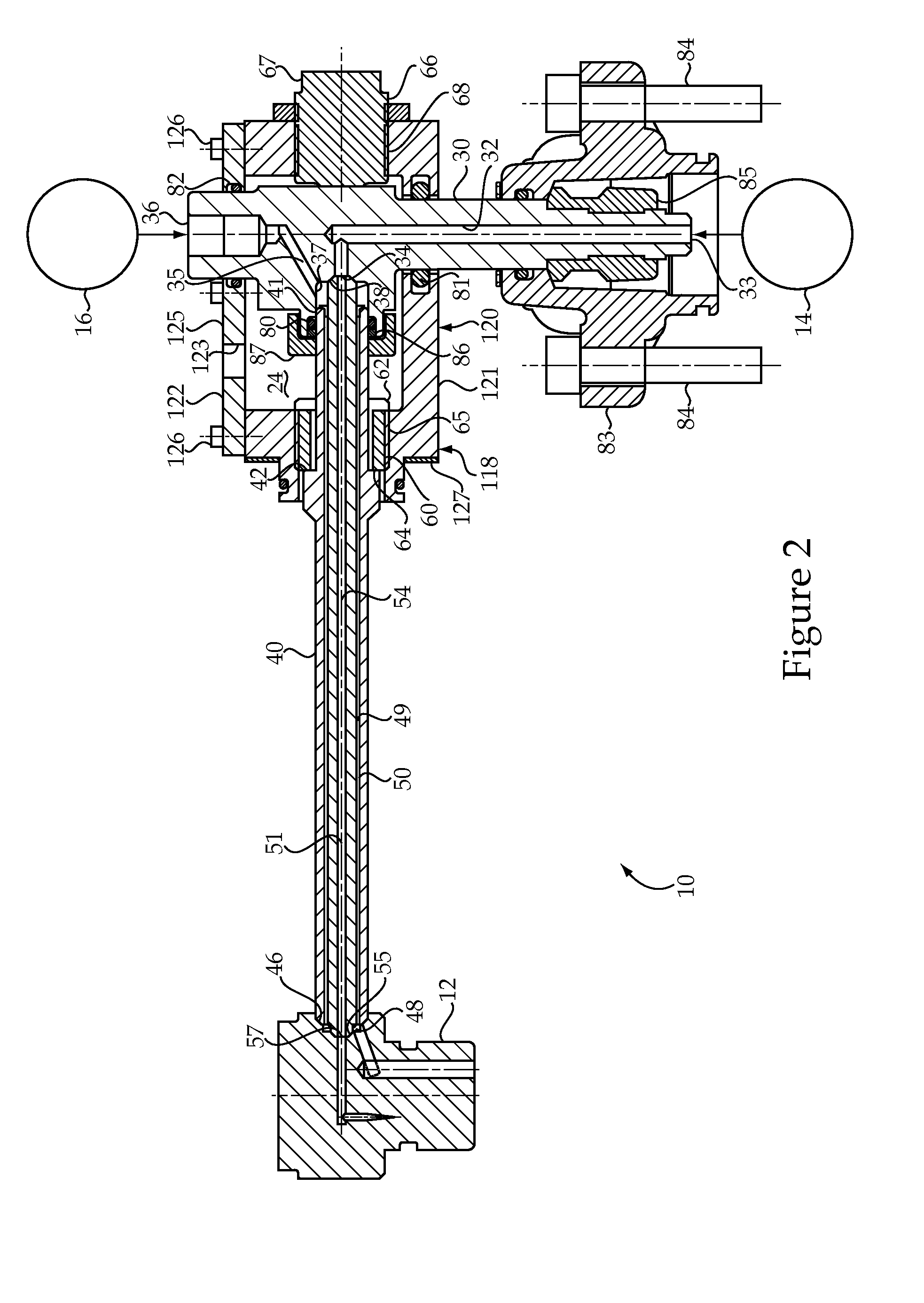
[0017]Referring to FIG. 1, an engine 5 according to the present disclosure utilizes a dual fuel common rail system 10. Engine 5 includes an engine housing 6 that defines a plurality of cylinders 7, only one of which is shown. The dual fuel system 10 includes a plurality of dual fuel injectors 12 (only one shown) that each include an injector body 70 with a tip component 71 positioned for direct injection of gaseous fuel and / or liquid fuel into one of the engine cylinders 7. The dual fuel system 10 includes a plurality of outer tubes 50 and inner tubes 40 that each extend into engine housing 6 between a quill 30 and one of the fuel injectors 12. Each of the inner tubes 50 is compressed between a conical seat on an associated quill 30 and a conical seat on one of the fuel injectors 12. Thus, each engine cylinder 7 has one associated fuel injector 12, one outer tube 40, one inner tube 50 and one quill 30. The dual fuel system 10 includes a gaseous fuel common rail 16 that is fluidly co...


PUM


Abstract

A method of operating an electronically controlled dual fuel compression ignition engine includes injecting a pilot ignition quantity of liquid fuel into an engine cylinder from a dual fuel injector in an engine cycle during an auto ignition condition. An amount of gaseous fuel is also injected into the engine cylinder from the dual fuel injector in the same engine cycle. The amount of gaseous fuel is divided between a pre-mix quantity of gaseous fuel, which may be injected about 90° before top dead center, and a post ignition quantity of gaseous fuel that may be injected after top dead center, with both quantities being greater than zero. An engine controller may change a ratio of the pre-mix quantity of gaseous fuel to the post ignition quantity of gaseous fuel responsive to changing from a first engine speed and load to a second engine speed and load. The pilot ignition quantity of liquid fuel is compression ignited, which in turn causes the gaseous fuel to be ignited. A pre-mix quantity of liquid fuel may also be included in order to speed the combustion process at higher engine speeds.

Description

TECHNICAL FIELD[0001]The present disclosure relates generally to electronically controlled dual fuel compression ignition engines, and more particularly to varying premixed and post ignition quantities of gaseous fuel injection responsive to changes in engine speed and load.BACKGROUND[0002]Gaseous fuel engines are known for their ability to burn clean relative to their compression ignition engine counterparts. However, gaseous fuels are well known for the difficulty in attaining successful ignition. Some gaseous fuel engines utilize a spark plug, whereas other engines are known for utilizing a small amount of distillate diesel fuel that is compression ignited to in turn ignite a larger charge of gaseous fuel. In these engines, the gaseous fuel may be supplied to the engine intake manifold or metered directly into individual cylinders where it is mixed with air prior to being ignited responsive to the pilot diesel injection near top dead center. While this strategy may reduce NOx due...

Claims


Application Information

Patent Timeline
Patent Type & Authority Applications(United States)
IPC IPC(8): F02D41/30F02M43/04
CPCF02D41/3035Y02T10/36F02D41/403F02M21/0287F02D19/061F02D19/0647F02D19/0684F02D19/0694F02D19/081F02D41/0027F02M21/0254Y02T10/44Y02T10/32F02M43/04F02M45/086F02M2200/44F02M2200/46F02M2200/701F02M63/0064F02D41/3094Y02T10/30Y02T10/40
Inventor MONTGOMERY, DAVID
Owner CATERPILLAR INC
Why Eureka
Try Eureka