
Computer-Based Method for Real-Time Three-Dimensional Geological Model Calculation and Reservoir Navigation

a computer-based method and geological model technology, applied in the direction of survey, directional drilling, borehole/well accessories, etc., can solve the problem that the plan does not take into account the geometry of the geological layers

Active Publication Date: 2012-12-27
BAKER HUGHES INC
View PDF9 Cites 10 Cited by
  • Summary
  • Abstract
  • Description
  • Claims
  • Application Information

AI Technical Summary

Problems solved by technology

However, most of the time, the planning does not take into account the geometry of the geological layers that may be traversed.

Method used


Image

  • Computer-Based Method for Real-Time Three-Dimensional Geological Model Calculation and Reservoir Navigation
  • Computer-Based Method for Real-Time Three-Dimensional Geological Model Calculation and Reservoir Navigation
  • Computer-Based Method for Real-Time Three-Dimensional Geological Model Calculation and Reservoir Navigation

Examples


Embodiment Construction

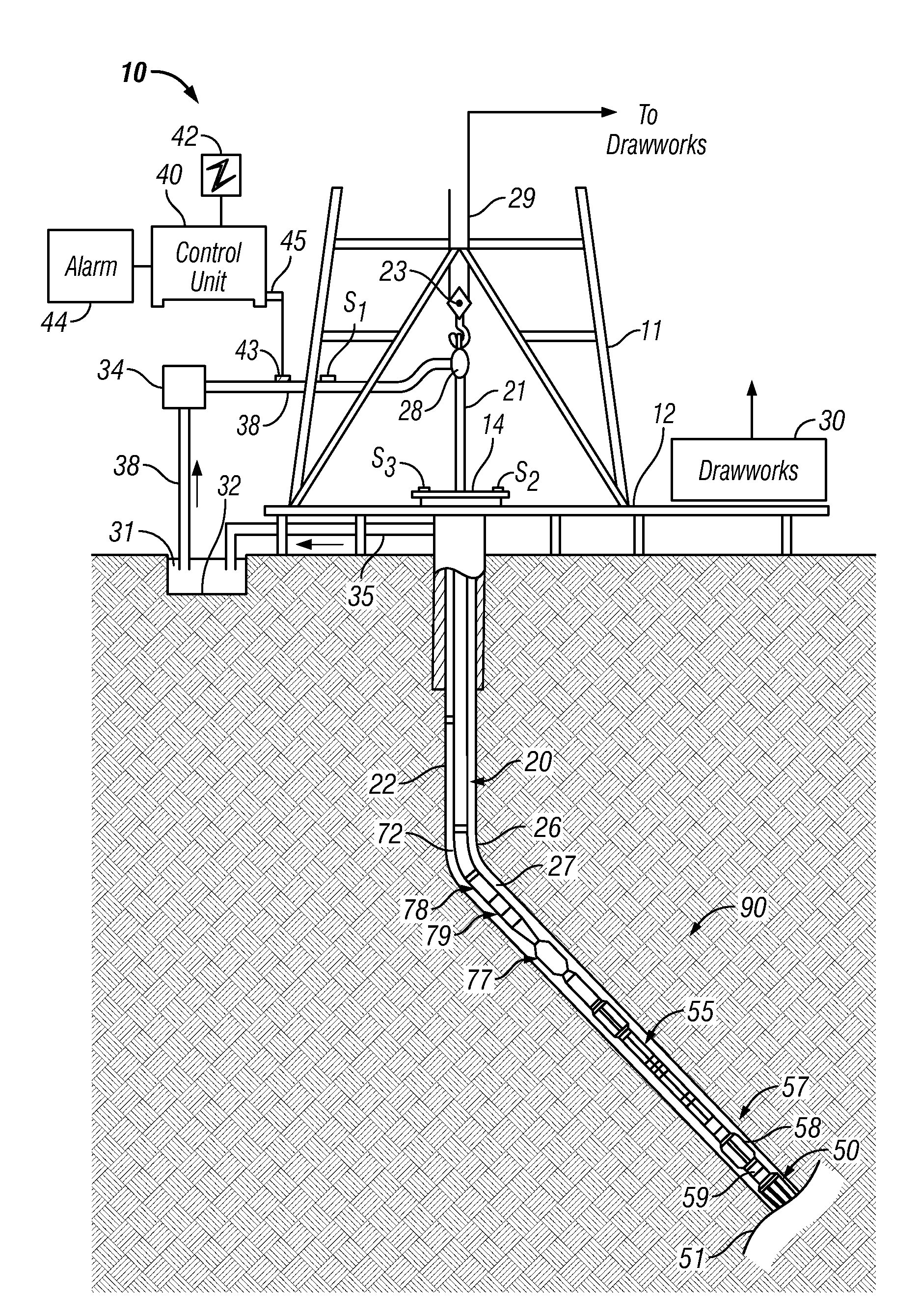
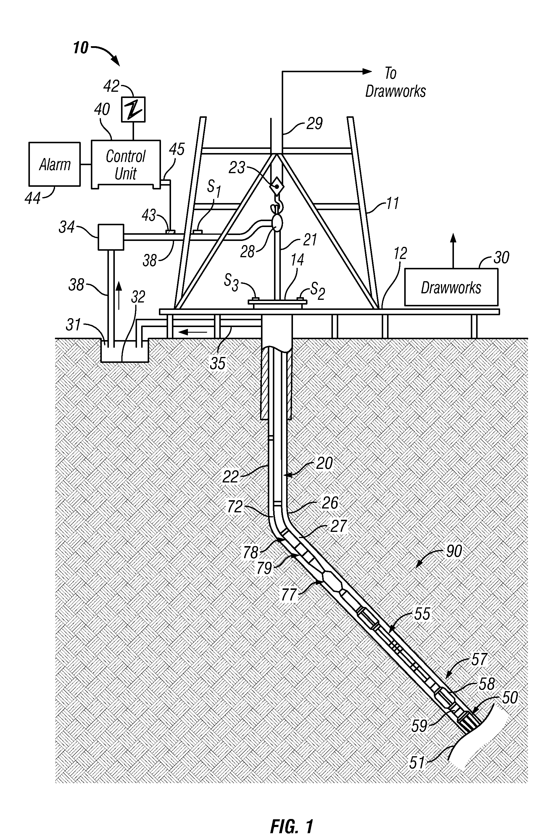
[0029]FIG. 1 shows a schematic diagram of a drilling system 10 with a drillstring 20 carrying a drilling assembly 90 (also referred to as the bottom hole assembly, or “BHA”) conveyed in a “wellbore” or “borehole”26 for drilling the wellbore. The drilling system 10 includes a conventional derrick 11 erected on a floor 12 which supports a rotary table 14 that is rotated by a prime mover such as an electric motor (not shown) at a desired rotational speed. The drillstring 20 includes a tubing such as a drill pipe 22 extending downward from the surface into the borehole 26. The drillstring 20 is pushed into the wellbore 26 when a drill pipe 22 is used as the tubing. For coiled-tubing applications, a tubing injector, such as an injector (not shown), however, is used to move the tubing from a source thereof, such as a reel (not shown), to the wellbore 26. The drill bit 50 attached to the end of the drillstring breaks up the geological formations when it is rotated to drill the borehole 26....


PUM


Abstract

A method of calculating a 3-D geologic model in real time using, as input, 2-D geologic data. The 3-D is used for conducting further drilling operations. The model may be updated in real time using additional measurements obtained during drilling operations.

Description

BACKGROUND OF THE DISCLOSURE[0001]1. Field of the Disclosure[0002]This disclosure relates generally to drilling of deviated wells into earth formations, and more particularly to using earth models built in real time for maintaining the drilling in a desired direction.[0003]2. Description of the Related Art[0004]Boreholes are usually drilled along predetermined paths and proceed through various formations. A drilling operator typically controls the surface-controlled drilling parameters during drilling operations. These parameters include weight on bit, drilling fluid flow through the drill pipe, drill string rotational speed (r.p.m. of the surface motor coupled to the drill pipe) and the density and viscosity of the drilling fluid. The downhole operating conditions continually change and the operator must react to such changes and adjust the surface-controlled parameters to properly control the drilling operations. For drilling a borehole in a virgin region, the operator typically r...

Claims


Application Information

Patent Timeline
IPC IPC(8): E21B7/00E21B47/00E21B7/04
CPCE21B44/00G01V99/00E21B49/00G01V20/00
Inventor LUXEY, PASCAL
Owner BAKER HUGHES INC
Learn More