Light emitting diode bulb

a technology of light-emitting diodes and light-emitting diodes, which is applied in the direction of discharge tube main electrodes, semiconductor devices of light sources, lighting and heating apparatus, etc., can solve the problems of unsatisfactory uniformity and light-emitting angle, affecting the position of leds in light-emitting bulbs, and limiting the light-emitting field. , to achieve the effect of wide angle, improved heat dissipation structur

Active Publication Date: 2012-12-27
AMTRAN TECH
View PDF3 Cites 14 Cited by
  • Summary
  • Abstract
  • Description
  • Claims
  • Application Information

AI Technical Summary

Benefits of technology

[0008]The invention provides a light emitting diode (LED) bulb which has a better heat dissipating structure and an illumination area with a wider angle and more uniformity.

Problems solved by technology

Furthermore, the position of the LED in the light bulb is affected and limited by the internal driving circuit and heat sink.
As such, when light provided by LEDs (not shown) in the bulb 100 passes through the lamp cover and is emitted from the bulb 100, the distribution of the light field is overly concentrated in the center such that the uniformity and the light emitting angle is not ideal.

Method used


Image

  • Light emitting diode bulb
  • Light emitting diode bulb
  • Light emitting diode bulb

Examples


Embodiment Construction

[0040]It is to be understood that the foregoing and other detailed descriptions, features, and advantages are intended to be described more comprehensively by providing embodiments accompanied with figures hereinafter. In the following embodiments, wordings used to indicate directions, such as “up,”“down,”“front,”“back,”“left,” and “right”, merely refer to directions in the accompanying drawings. Therefore, the directional wording is used to illustrate rather than limit the invention.

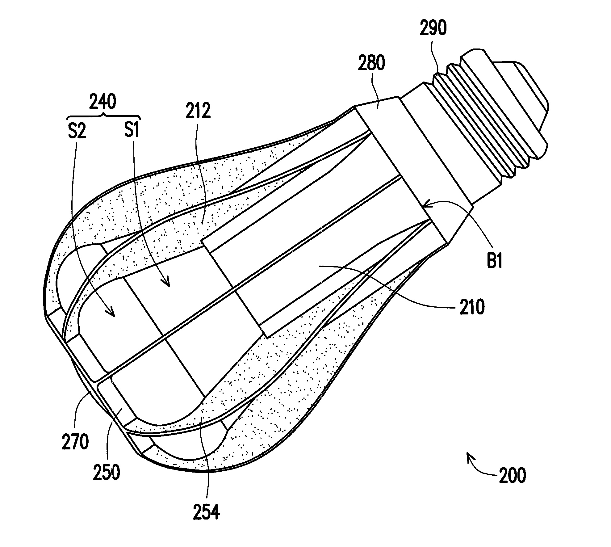
[0041]FIG. 2A is a schematic perspective view of an LED bulb according to an embodiment of the invention. FIG. 2B is a schematic breakdown view of the LED bulb shown in FIG. 2A. FIG. 3A illustrates a partial schematic cross-sectional view showing the progression of light beams of the LED bulb in FIG. 2A. FIG. 3B is a schematic view of a light field distribution of the LED bulb shown in. FIG. 2A. Referring to FIG. 2A, FIG. 2B, FIG. 3A, and FIG. 3B at the same time, a light emitting diode (LED) bulb 200 o...


PUM


Abstract

A light emitting diode bulb including a heat sink, a light source plate, a reflective frame and a secondary optical component is provided. The light source plate includes a circuit board disposed on the heat sink and a plurality of light emitting devices disposed on the circuit board. The reflective frame disposed on the light source plate includes a plate portion and a reflective pillar. The plate portion has a plurality of openings exposing the light emitting devices. The secondary optical component has a first optical surface and a second optical surface. An absolute value of the slope of a tangent line of any point on the first optical surface with respect to the heat sink is constant. An absolute value of the slope of a tangent line of any point on the second optical surface is gradually smaller along the direction away from the heat sink.

Description

CROSS-REFERENCE TO RELATED APPLICATION[0001]This application claims the priority benefit of Taiwan application serial no. 100122277, filed on Jun. 24, 2011. The entirety of the above-mentioned patent application is hereby incorporated by reference herein and made a part of this specification.BACKGROUND OF THE INVENTION[0002]1. Field of the Invention[0003]The invention relates to a light source. More particularly, the invention relates to a light emitting diode (LED) bulb having uniform brightness.[0004]2. Description of Related Art[0005]The light emitting diode (LED) is extensively used in light bulbs, and such development matches the trend for low power consumption and environmental protection. However, since the LED has the light source output characteristics such as spot light source, high brightness, and narrow light beams, and considerations such as mechanical properties and product reliability for LED differ from traditional lamp products, countries all over the world are deve...

Claims


Application Information

Patent Timeline
Patent Type & Authority Applications(United States)
IPC IPC(8): H01J7/24
CPCF21V3/02F21K9/135F21K9/232
Inventor YU, HUNG-TA
Owner AMTRAN TECH
Why Eureka
Try Eureka