
Direct-incidence optical-electrical connection device

Inactive Publication Date: 2012-12-27
ALL BEST PRECISION TECH
View PDF2 Cites 0 Cited by
  • Summary
  • Abstract
  • Description
  • Claims
  • Application Information

AI Technical Summary

Benefits of technology

[0005]It is an objective of the present invention to provide a direct-incidence optical-electrical connection device for allowing, after coupling the direct-incidence optical-electrical connection device to optical fibers, an optical signal and an electrical signal to undergo optical-electrical conversion and optical-electrical connection directly without going through secondary optical conversion (such as reflection, refraction, diffraction, and diffusion) so as to cut costs, streamline a manufacturing process, and reduce wear and tear.
[0014]Compared with the prior art, the present invention provides a direct-incidence optical-electrical connection device that comprises an optical connection unit directly coupled to optical fibers. An optical signal being transmitted within the optical fibers is directly sent to a communication unit and thus incurs little coupling loss (arising from diffraction or diffusion, for example), so as to effectuate conversion between an optical signal and an electrical signal, efficient optical-electrical coupling, and enable the subsequent processing of the optical signal and the electrical signal.

Problems solved by technology

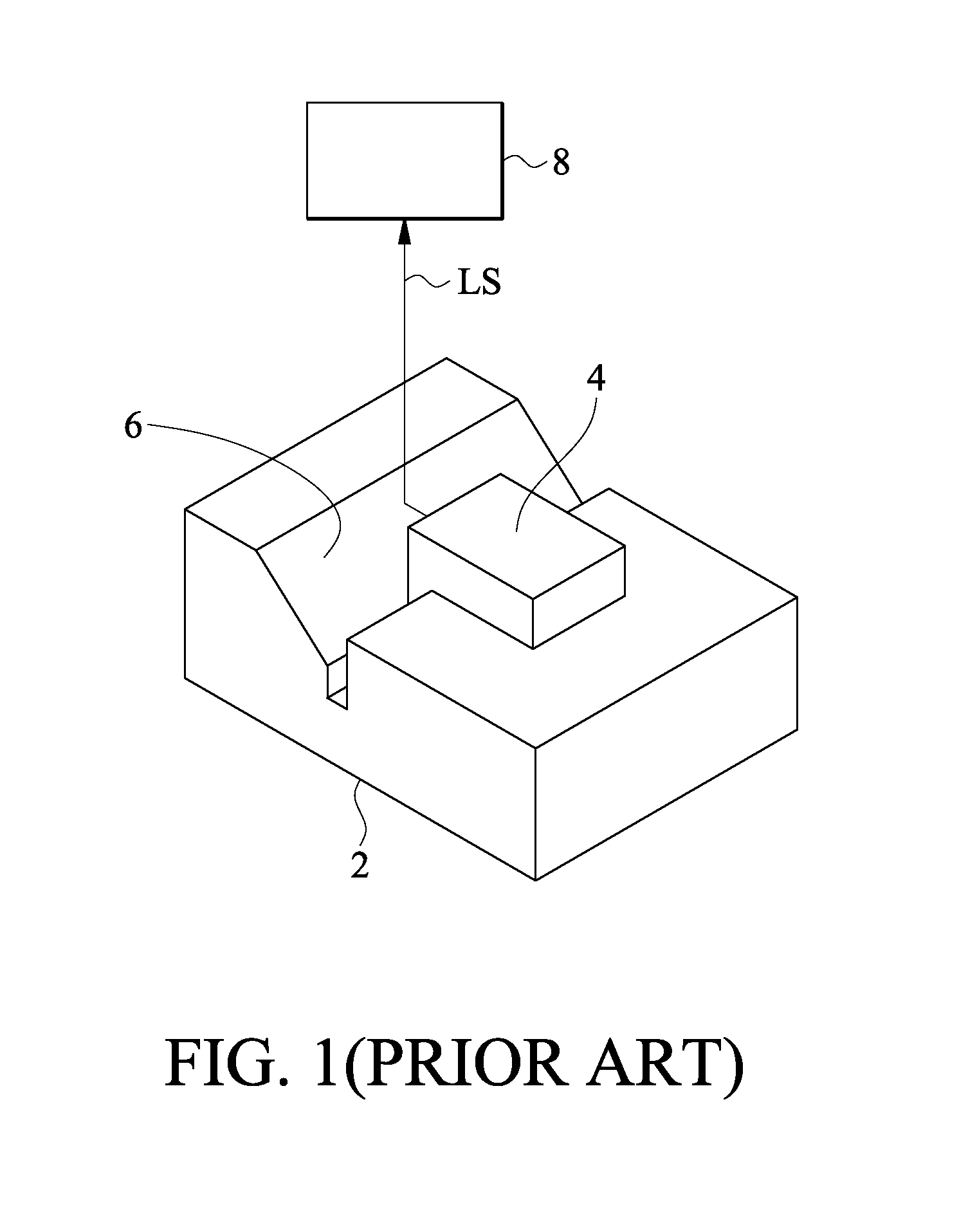
Nonetheless, persons skilled in the art should understand that the optical signal LS that undergoes secondary optical conversion inevitably incurs optical loss resulting from reflection, diffraction, and diffusion; as a result, the optical signal LS is likely to go wrong at a light-receiving end 8, thus resulting in an increase in the bit error rate (BER).

Method used


Image

  • Direct-incidence optical-electrical connection device
  • Direct-incidence optical-electrical connection device
  • Direct-incidence optical-electrical connection device

Examples


Embodiment Construction

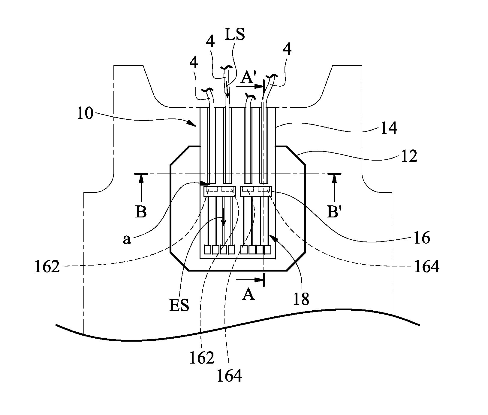
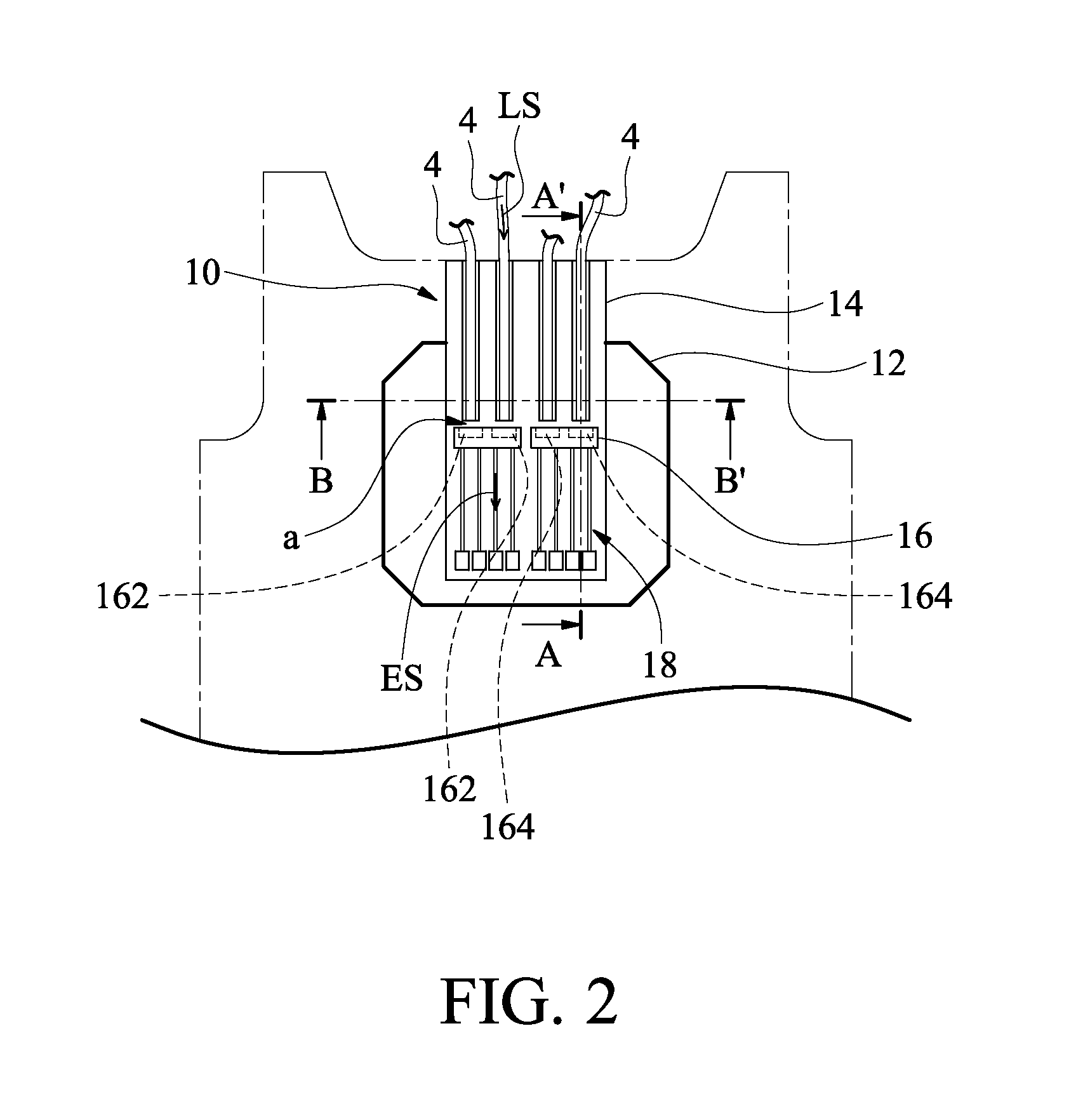
[0020]Referring to FIG. 2, there is shown a schematic view of the structure of a direct-incidence optical-electrical connection device according to an embodiment of the present invention. As shown in FIG. 2, the direct-incidence optical-electrical connection device 10 is coupled to a plurality of optical fibers 4 to convert an optical signal LS in the optical fibers 4 into an electrical signal ES. The optical fibers 4 are single-mode fibers or multi-mode fibers.

[0021]The direct-incidence optical-electrical connection device 10 comprises a substrate 12, an optical connection unit 14, a communication unit 16, and an electrical connection unit 18. The substrate 12 underpins the optical connection unit 14, the communication unit 16, and the electrical connection unit 18. For example, the substrate 12 is a semiconductor substrate or a printed circuit substrate.

[0022]The optical connection unit 14 is disposed on the substrate 12. The optical connection unit 14 is connected to the optical ...


PUM


Abstract

A direct-incidence optical-electrical connection device for coupling to optical fibers and thereby converting an optical signal in the optical fibers into an electrical signal includes a substrate, an optical connection unit, a communication unit, and an electrical connection unit. The optical connection unit, the communication unit, and the electrical connection unit are disposed on the substrate. The optical connection unit connects the optical fibers. The communication unit is vertically disposed at an end of an edge of the optical connection unit. The ends of the optical fibers correspond directly to the communication unit for admitting the optical signal. Then, by optical-electrical conversion (OEC), the optical signal is converted into an electrical signal to be sent to the electrical connection unit. Then, the electrical signal from the electrical connection unit is converted into an optical signal to be sent to the optical connection unit via the communication unit.

Description

FIELD OF THE INVENTION[0001]The present invention relates to optical-electrical connection devices, and more particularly, to a direct-incidence optical-electrical connection device directly coupled to optical fibers for performing optical-electrical conversion and optical-electrical connection.BACKGROUND OF THE INVENTION[0002]A conventional optical-electrical connector enables an optical fiber to be coupled to an electronic circuit, such that an optical signal is converted into an electrical signal by an optical-electrical conversion unit disposed in the optical-electrical connector, thereby not only allowing a back-end electronic circuit to perform a subsequent electrical signal processing process, but also converting the electrical signal into the optical signal by means of an electrical-optical conversion unit to thereby effectuate electrical-optical communication and optical-electrical communication.[0003]However, as shown in FIG. 1, an optical-electrical connector 2 is coupled...

Claims


Application Information

Patent Timeline
IPC IPC(8): G02B6/43
CPCG02B6/4202G02B6/4284G02B6/4246
Inventor YANG, HAVEN
Owner ALL BEST PRECISION TECH
Learn More