Glossing device, fixing device, and image forming apparatus incorporating same

Inactive Publication Date: 2012-12-27
RICOH KK
View PDF1 Cites 11 Cited by
  • Summary
  • Abstract
  • Description
  • Claims
  • Application Information

AI Technical Summary

Benefits of technology

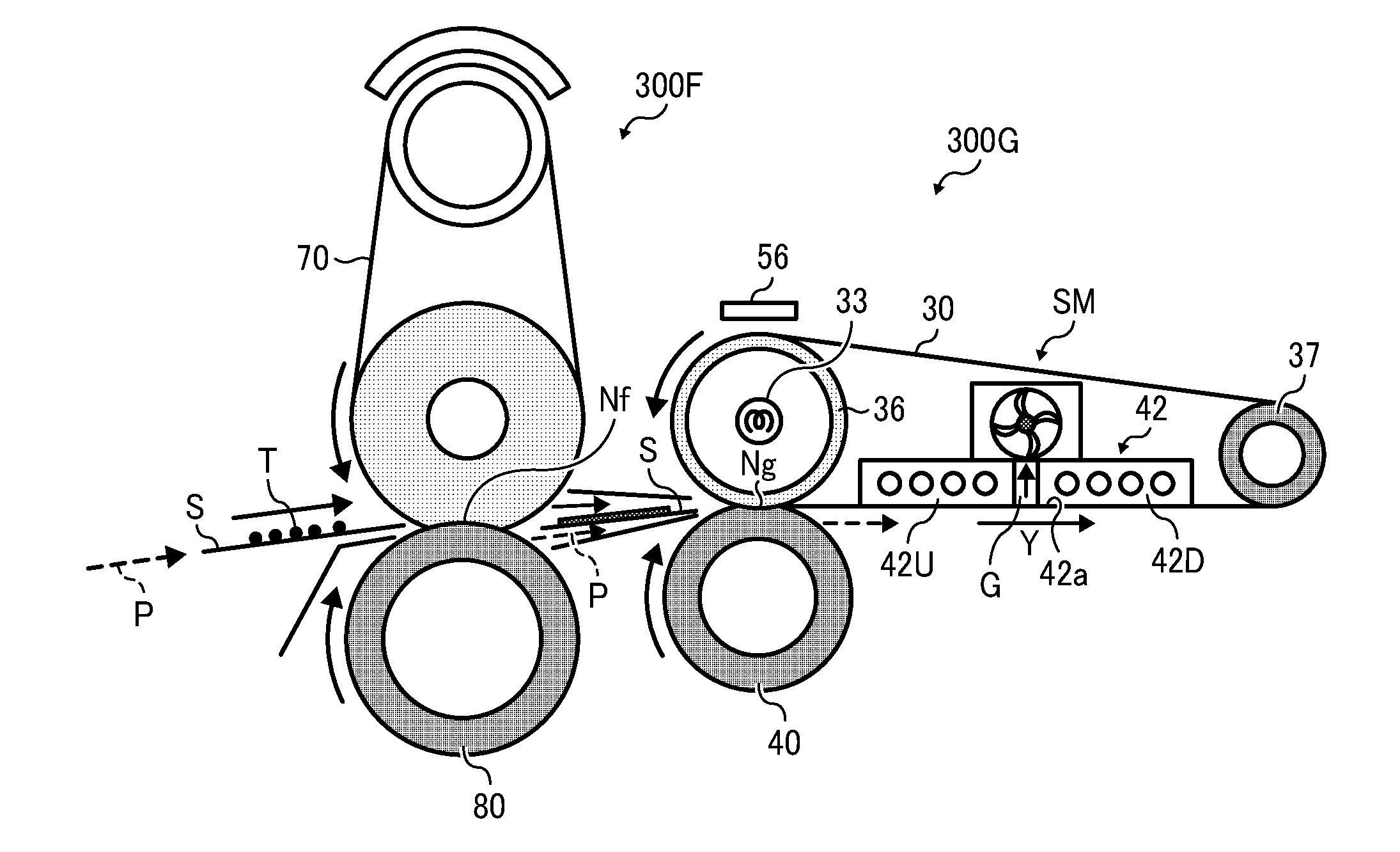
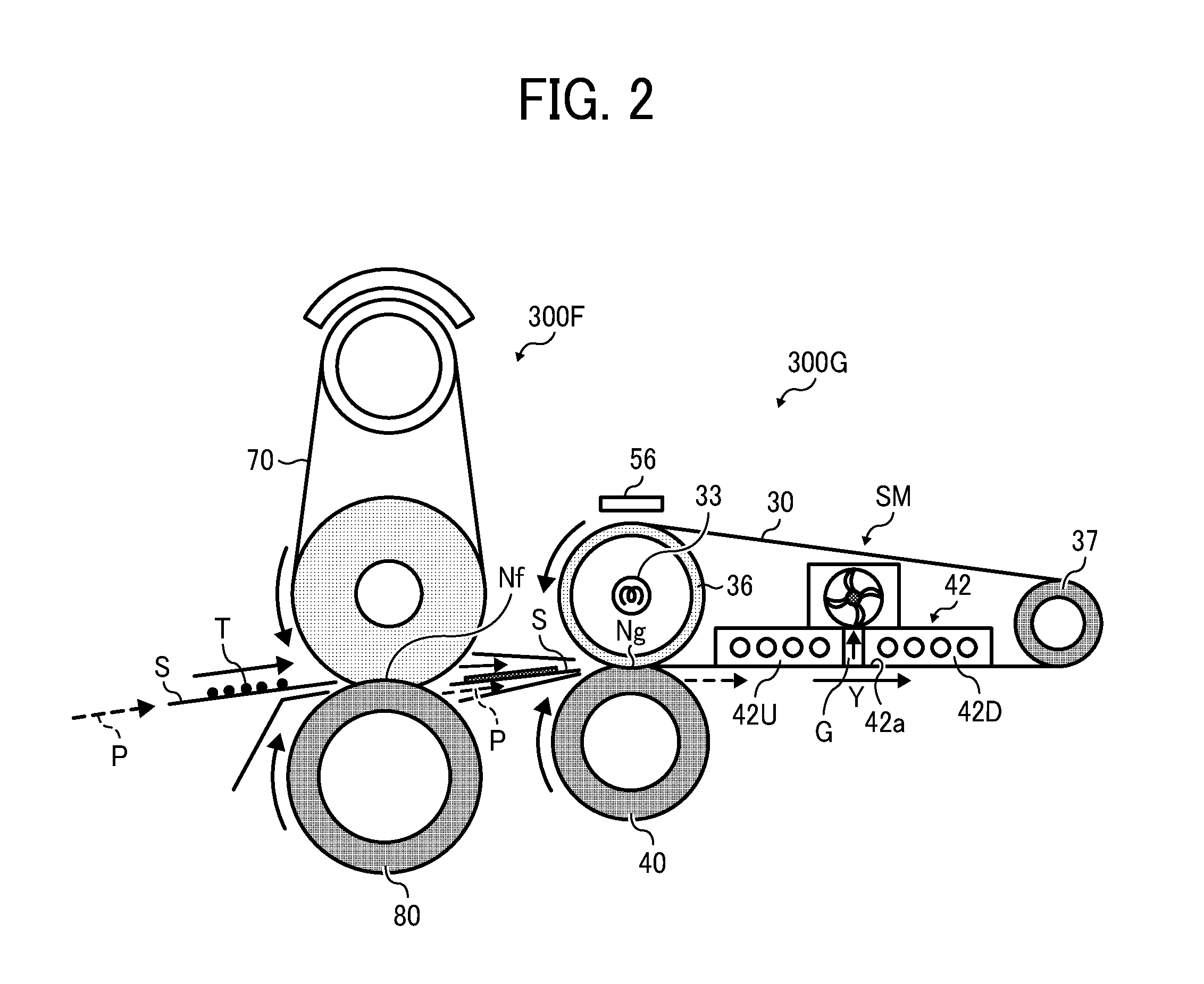
[0011]To date, belt-based fixing devices are designed with a belt cooler for cooling an endless rotary belt during conveyance of a recording medium downstream from a fixing nip, so as to provide uniform cooling and proper separation of the recording medium from the belt after fixing and glossing a toner image thereon.

Problems solved by technology

Keeping the fixing belt in proper tension prevents the belt from deformation due to being held on the supporting rollers for extended periods of time, as well as sags and creases resulting from thermal expansion / contraction of the belt material subjected to repeated heating and cooling cycles, which would otherwise affect uniformity of gloss across a resulting image.
That is, tightening the belt in the longitudinal direction to establish close contact between the belt and the cooler increases the torque required to drive the belt.
Further, increased longitudinal tension in the belt can lead to accelerated wear and tear of the adjoining surfaces of the belt and the belt cooler, which slide against each other during rotation of the belt.

Method used


Image

  • Glossing device, fixing device, and image forming apparatus incorporating same
  • Glossing device, fixing device, and image forming apparatus incorporating same
  • Glossing device, fixing device, and image forming apparatus incorporating same

Examples


first embodiment

[0068]FIG. 3 is a top plan view of the glossing unit 300G including the suction mechanism SM according to this patent specification.

[0069]As shown in FIG. 3, in the present embodiment, the suction mechanism SM comprises a single suction source 50 formed of an elongated duct 51 extending generally parallel to and in fluid communication with the gap G between the mutually spaced cooling elements 42U and 42D, and a fan 52 connected to the duct 51 to exhaust air from the gap G through the duct 51 to generate a negative pressure within the gap G.

[0070]Specifically, the duct 51 may be configured as a longitudinally slotted, perforated, or otherwise open tube or pipe, having a longitudinal opening and at least one open end, which is positioned on the belt cooler 42 with its longitudinal opening directed to the gap G between the cooling elements 42U and 42D, and its open end coupled with the fan 52. The fan 52 may be any suitable device that can create an air flow from inside to outside the...

second embodiment

[0072]FIG. 4 is a top plan view of the glossing unit 300G including the suction mechanism SM according to this patent specification.

[0073]As shown in FIG. 4, the overall configuration of the present embodiment is similar to that depicted primarily with reference to FIG. 3, except that the suction mechanism SM includes, instead of a single suction source, a pair of first and second suction sources 50A and 50B directed to two opposite side sections of the gap G opposite to each other in the transverse direction X of the belt 30, as well as a controller 60 operatively connected with the suction sources 50A and 50B to independently adjust a suction force exerted by each suction source at each associated section of the gap G.

[0074]Specifically, in the present embodiment, each of the paired suction sources 50A and 50B is formed of a relatively short duct 51 extending generally parallel to and in fluid communication with the gap G between the cooling elements 42U and 42D, and a fan 52 conn...

third embodiment

[0077]FIG. 5 is a top plan view of the glossing unit 300G including the suction mechanism SM according to this patent specification.

[0078]As shown in FIG. 5, the overall configuration of the present embodiment is similar to that depicted primarily with reference to FIG. 4, except that the suction mechanism SM further includes a displacement sensor 61 disposed adjacent to the belt 30 to detect an amount of displacement by which the belt displaces from a proper operational position thereof in the transverse direction X of the belt 30, as well as a third suction source 50C directed to a central section between the two opposite side sections of the gap G.

[0079]Specifically, in the present embodiment, the displacement sensor 61 comprises any suitable device that can measure the position and / or change in position of the glossing belt 30, which may be deployed, for example, at one longitudinal end of the belt assembly to detect displacement of the edge of the belt 30. The third suction sou...


PUM


Abstract

A glossing device includes a first roller, a second roller, an endless rotary belt, a third roller, a heater, a belt cooler, and a suction mechanism. The second roller is disposed parallel to the first roller. The endless rotary belt is looped for rotation around the first and second rollers. The third roller is disposed opposite the first roller via the belt. The heater is disposed adjacent to the belt to heat the belt. The first and third rollers press against each other via the belt to form a nip therebetween. The belt cooler is disposed inside the loop of the belt downstream from the first roller and upstream from the second roller for cooling the belt. The belt cooler includes at least two mutually spaced cooling elements that together form a gapped contact surface for establishing thermal contact with the belt.

Description

CROSS-REFERENCE TO RELATED APPLICATION[0001]This patent application claims priority pursuant to 35 U.S.C. §119 to Japanese Patent Application No. 2011-137464, filed on Jun. 21, 2011, the entire disclosure of which is hereby incorporated by reference herein.BACKGROUND OF THE INVENTION[0002]1. Technical Field[0003]The present invention relates to a glossing device, a fixing device, and an image forming apparatus incorporating the same, and more particularly, to a fixing device that processes a toner image with heat and pressure on a recording medium for imparting gloss, and an electrophotographic image forming apparatus, such as a photocopier, facsimile machine, printer, plotter, or multifunctional machine incorporating several of these features, which incorporates such a fixing device with a glossing capability.[0004]2. Background Art[0005]In electrophotographic image forming apparatuses, such as photocopiers, facsimile machines, printers, plotters, or multifunctional machines incorp...

Claims


Application Information

Patent Timeline
IPC IPC(8): G03G15/20
CPCG03G15/0189G03G15/2021G03G2215/0132G03G2215/00805G03G15/6585
Inventor KUNII, HIROYUKIAMITA, AKIYASUMURAMATSU, SATOSHITOMITA, KUNIHIKO
Owner RICOH KK
Why Eureka
Try Eureka