Rotational joint

a rotational joint and shaft technology, applied in mechanical devices, couplings, instruments, etc., can solve the problems of insufficient displacement of flashes from optical axes in the prior art, substantially narrow and miniaturized rotational joints, and reduce the size of camera bodies, reduce the length of the shaft in the pop-up or the lift-up mechanism, and reduce the size of the camera body

Active Publication Date: 2012-12-27
RICOH IMAGING COMPANY
View PDF7 Cites 29 Cited by
  • Summary
  • Abstract
  • Description
  • Claims
  • Application Information

AI Technical Summary

Benefits of technology

[0005]As the size of the camera is reduced, the position of the built-in flash on the camera body gets closer to the photographing optical axis, thus the vignetting effect and the red-eye effect increases. In particular, for a compact interchangeable-lens camera, these effects are substantial when a short focal-length lens

Problems solved by technology

However, as the size of the camera body is reduced, the length of the shaft in the pop-up or the lift-up mechanism is also reduced, thereby the displacement of the flash from the optic

Method used


Image

  • Rotational joint
  • Rotational joint
  • Rotational joint

Examples


Embodiment Construction

[0032]The present invention is described below with references to the embodiments shown in the drawings.

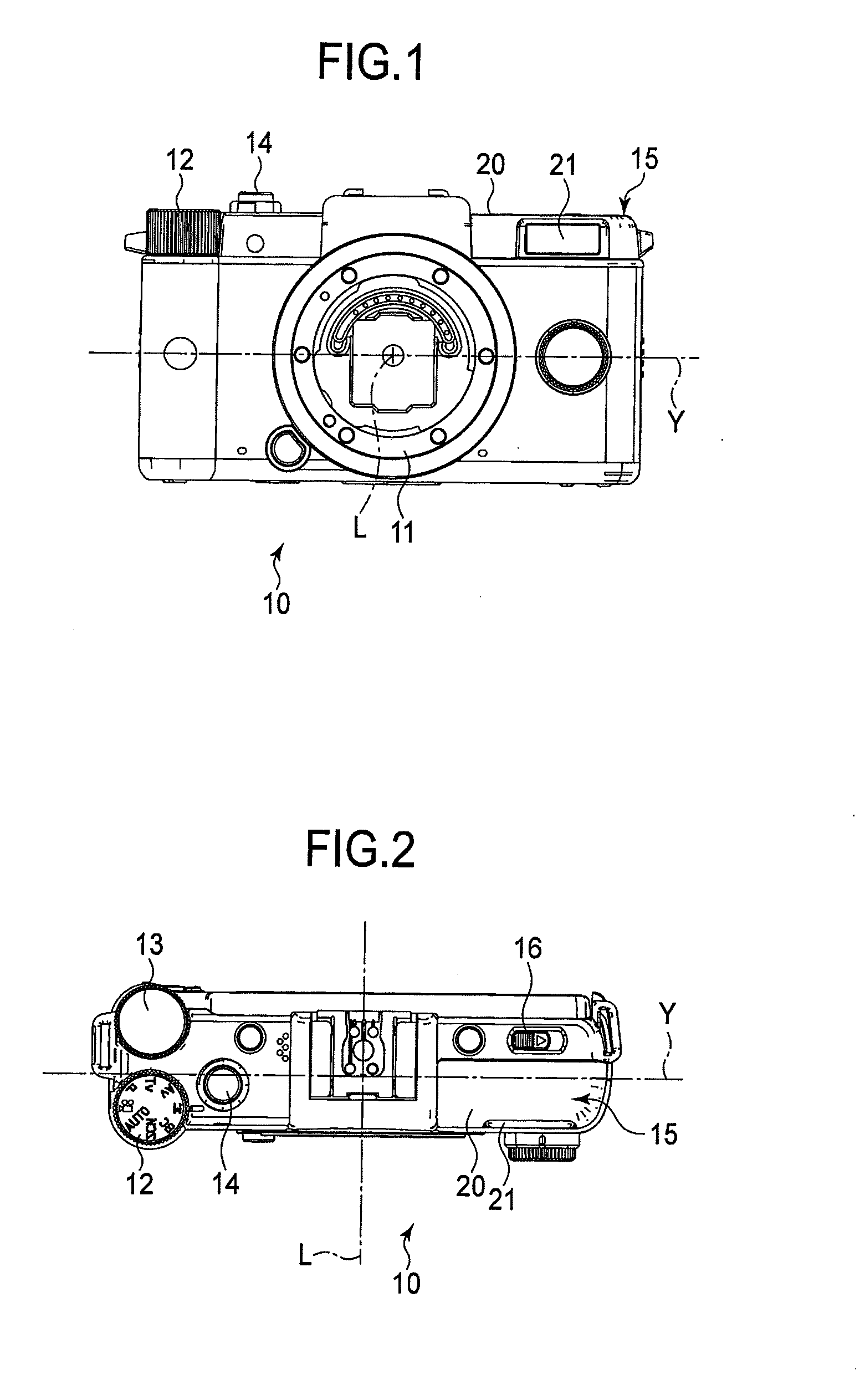
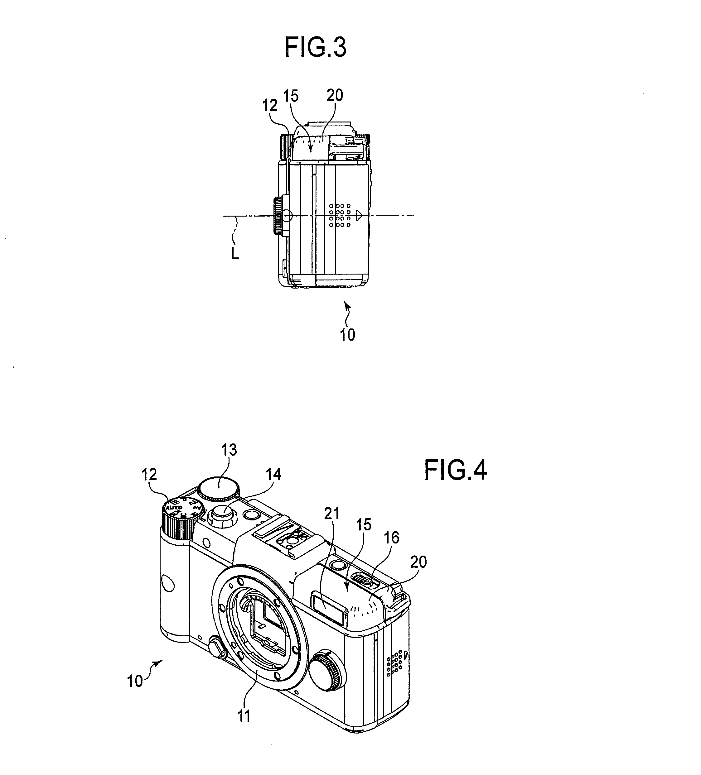
[0033]FIGS. 1-4 are a front elevational view, a top plan view, a right side elevational view and a front perspective view of a compact camera to which a rotational joint of an embodiment of the present invention is applied. The rotational joint of the present embodiment is applied to the pop-up mechanism for a built-in flash. Incidentally, in FIGS. 1-4, the pop-up mechanism is retracted inside the camera body.

[0034]The compact camera of this embodiment may be an interchangeable-lens digital camera. A lens mount 11 for connecting a lens barrel may be provided in the center of the front face of the camera body 10. For example, as shown in the front elevational view and the top plan view, a mode dial 12, an E-dial or a shaft encoder 13 and a release button 14 are provided on the left-hand side of the camera body 10, while a built-in flash unit 15 is provided on the front right-hand s...


PUM


Abstract

A rotational joint is provided that comprises a first member, second member, rotational shaft member, rotational biasing member and stop ring. The first member has a pair of sidewalls that face each other. The second member has a pair of plate members each disposed proximate to the outer-facing sides of the sidewalls. The rotational shaft member is fitted into shaft holes in each of the plate members and the sidewalls. The rotational biasing member is disposed around the rotational shaft member and its one end is engaged with the first member and the other end with the stop ring fixed to the rotational shaft member. The first member is rotatable with respect to the rotational shaft member that is fixed to the second member. The rotational biasing member and stop ring are disposed between the sidewalls.

Description

BACKGROUND OF THE INVENTION[0001]1. Field of the Invention[0002]The present invention relates to a rotational joint that is provided with a biasing member and used for connecting two members that are rotatable with respect to one another.[0003]2. Description of the Related Art[0004]Some cameras are configured with a built-in flash that pops out from the camera body when illuminating a scene requires a flash of light. By positioning the flash as far as possible from the photographing optical axis, vignetting and red-eye effect caused by light emitted from the flash device can be prevented. For example, a pop-up mechanism may include a shaft with the flash on its tip. The shaft is slidable in the vertical direction and biased upward by a spring. When retracting the flash, the shaft is retracted inside the camera body and its position is fixed by an engaging mechanism. When shooting with the flash, a user manipulates a slider knob that releases the engagement, thus the spring pushes up...

Claims


Application Information

Patent Timeline
IPC IPC(8): F16C11/04
CPCG03B15/05Y10T403/32541G03B2215/0507
Inventor AKIYAMA, KAZUHIRO
Owner RICOH IMAGING COMPANY
Why Eureka
Try Eureka