
Surgical instrument

a surgical instrument and a technology for reducing which is applied in the field of surgical instruments, can solve the problem of not being able to reduce the overall diameter of the surgical instrumen

Inactive Publication Date: 2012-12-27
ADEN LTD
View PDF27 Cites 69 Cited by
  • Summary
  • Abstract
  • Description
  • Claims
  • Application Information

AI Technical Summary

Benefits of technology

[0014]To overcome the above problem, an aspect of the present invention provides a surgical instrument that may decrease a surgery portion of a patient to be as small as possible by forming a wrist joint on a rear idler pulley between a front idler pulley and the rear idler pulley and reducing a diameter of the front idler pulley, thereby leading to reducing the overall diameter of the surgical instrument.
[0015]Another aspect of the present invention also provides a surgical instrument that may minutely control an end effector by applying small operation power to a wire since a diameter of a capstan may be formed to be large by reducing the diameter of the front idler pulley.
[0016]Another aspect of the present invention also provides a surgical instrument that may enhance reliability of a surgical instrument by decreasing operation power to be applied to a wire and thereby enhancing durability of the wire.
[0017]According to a first embodiment of the present invention, there is provided a surgical instrument including: a shaft; a wrist member including a guide member, a wrist body connected to the guide member and formed with a plurality of installation holes, and a plurality of protruding members each disposed to face the wrist body and having an insertion groove, and connected to the shaft; a plurality of effectors connected to the wrist member by a pin; a support driving unit having first through fourth rotation members inserted into pins that are mounted on the wrist member, respectively, and first and second wires connected to the plurality of effectors and the first through fourth rotation members, respectively; and a main driving unit including first through third main driving units. The main driving unit enables the entire wrist member to perform a yaw motion by rotating the entire wrist member, and enables the plurality of effectors to perform a pitch motion by simultaneously rotating the plurality of effectors into a single direction, and enables the plurality of effectors to perform a forceps motion of rotating into a direction increasing or decreasing a distance between the plurality of effectors.
[0018]According to a second embodiment of the present invention, there is provided a surgical instrument including: a shaft; a wrist member including a guide member, a wrist body connected to the guide member and formed with a plurality of installation holes, and a plurality of protruding members each disposed to face the wrist body and having an insertion groove, and connected to an effector; a plurality of effectors connected to the wrist member by a pin; a support driving unit having first through fourth rotation members inserted into pins that are mounted on the wrist member, respectively, and first and second wires sequentially connected to the plurality of effectors and the first through fourth rotation members, respectively; and a main driving unit connected to the support driving unit and mounted to be twisted with respect to the plurality of effectors. The main driving unit enables the entire wrist member to perform a yaw motion by rotating the entire wrist member, and enables the plurality of effectors to perform a pitch motion by simultaneously rotating the plurality of effectors into a single direction, and enables the plurality of effectors to perform a forceps motion of rotating into a direction increasing or decreasing a distance between the plurality of effectors.

Problems solved by technology

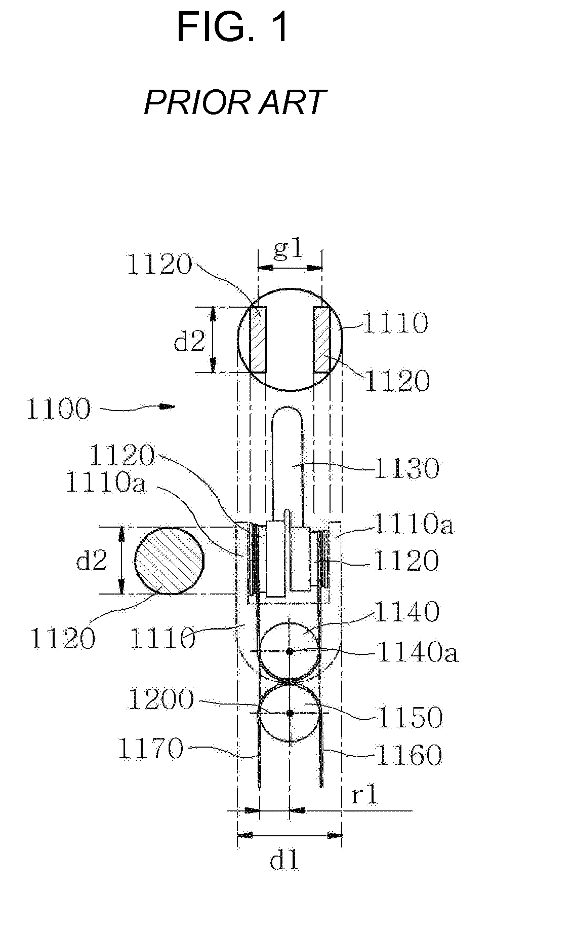
Accordingly, the conventional surgical instrument has a problem that it is impossible to reduce the overall diameter of the surgical instrument.

Method used


Image

  • Surgical instrument
  • Surgical instrument
  • Surgical instrument

Examples


first embodiment

[0031]Reference will now be made in detail to embodiments of the present invention, examples of which are illustrated in the accompanying drawings, wherein like reference numerals refer to the like elements throughout. Hereinafter, a surgical instrument according to the present invention will be described with reference to the accompanying drawings.

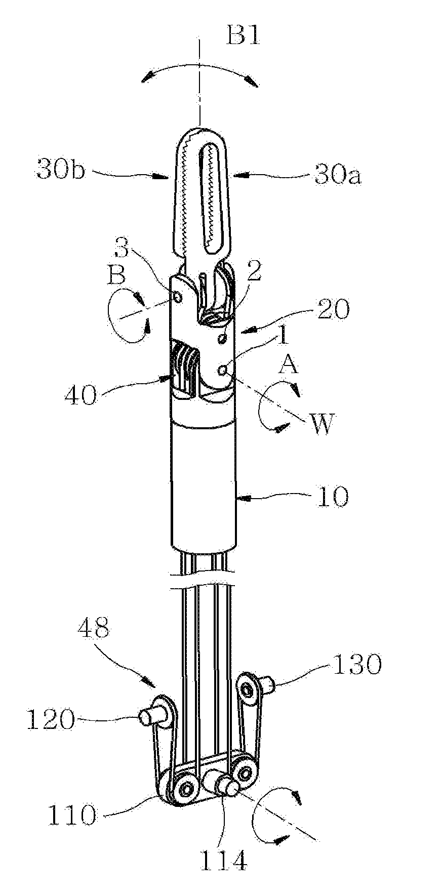
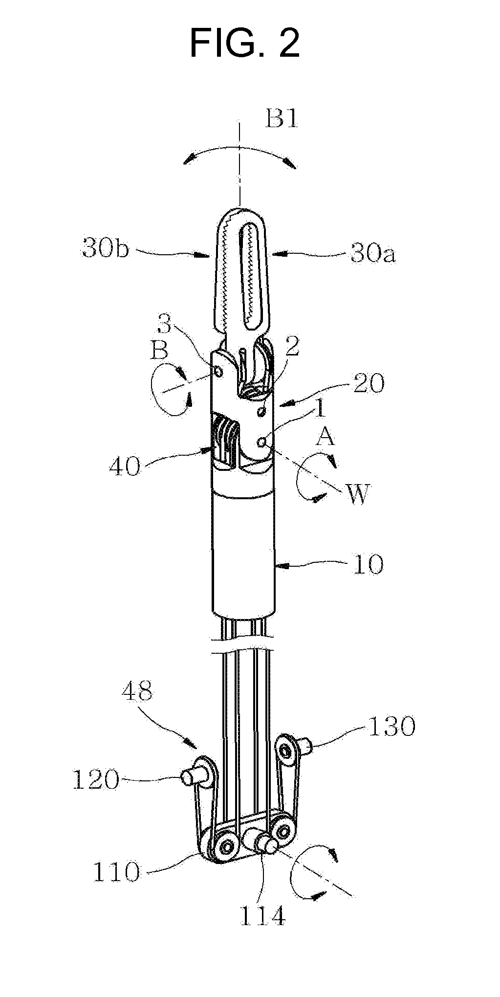
[0032]FIG. 2 is a perspective view illustrating an assembly state of a surgical instrument of the present invention, FIG. 3 is a perspective view illustrating a portion of the surgical instrument being exploded of FIG. 2, FIG. 4 is an exploded perspective view illustrating a driving unit of FIG. 3, and FIG. 5 is a view illustrating another embodiment of a driving unit of FIG. 3.

[0033]The surgical instrument according to the first embodiment of the present invention includes a shaft 10, a wrist member 20, a plurality of effectors 30a and 30b, a support driving unit 40, and a main driving unit 48 including first through third main driving u...

second embodiment

[0059]Hereinafter, a surgical instrument according to the present invention will be described with reference to the accompanying drawings.

[0060]FIG. 9 is a perspective view illustrating an assembly state of a surgical instrument according to the second embodiment of the present invention, and FIG. 10 is a view illustrating another embodiment of a driving unit of FIG. 9.

[0061]The surgical instrument according to the second embodiment of the present invention includes a shaft 10, a wrist member 20, a plurality of effectors 30a and 30b, a support driving unit 40, and a main driving unit 48. Here, the wrist member 20 and the plurality of effectors 30a and 30b may be configured to be similar to the first embodiment of the present invention and thus, a further detailed description related thereto will be omitted here.

[0062]The support driving unit 40 according to the second embodiment of the present invention includes a first rotation member 41, a second rotation member 42, a third rotati...


PUM


Abstract

Provided is a surgical instrument, including: a shaft; a wrist member including a guide member, a wrist body connected to the guide member and formed with a plurality of installation holes, and a plurality of protruding members each disposed to face the wrist body and having an insertion groove, and connected to the shaft; a plurality of effectors each connected to the wrist member by a pin; a support driving unit having first through fourth rotation members inserted into pins that are mounted on the wrist member, respectively, and each first and second wires connected to the plurality of effectors and the first through fourth rotation members, respectively; a main driving unit connected to the support driving unit by wire and having at least one driving unit. The main driving unit enables the entire wrist member to perform a yaw motion by rotating the entire wrist member, and enables the plurality of effectors to perform a pitch motion by simultaneously rotating the plurality of effectors into a single direction, and enables the plurality of effectors to perform a forceps motion of rotating into a direction increasing or decreasing a distance between the plurality of effectors.

Description

BACKGROUND OF THE INVENTION[0001]1. Field of the Invention[0002]The present invention relates to a surgical instrument, and more particularly, to a surgical instrument that may decrease the overall diameter of a surgical instrument by forming a wrist joint on a rear idler pulley between a front idler pulley and the rear idler pulley and thereby making it possible to decrease a diameter of the front idler pulley.[0003]2. Description of the Related Art[0004]To reduce a period of recuperation of a patient by minimizing an incision during an operation, a surgical instrument for surgery department may be applied to a laparoscopic surgery or a robot surgery. The surgical instrument for surgery department may be applied to the laparoscopic surgery or the robot surgery and hereinafter, may be simply referred to as a surgical instrument.[0005]The conventional art associated with the surgical instrument is already disclosed in the U.S. Pat. No. 5,792,135 that is registered in Aug. 6, 1998, an...

Claims


Application Information

Patent Timeline
Patent Type & Authority Applications(United States)
IPC IPC(8): A61B17/00
CPCA61B19/22A61B2019/2242A61B2019/2234A61B34/70A61B34/71A61B2034/305
Inventor YIM, JIN WHAN
Owner ADEN LTD
Learn More