Control apparatus, control method, and control program for elastic actuator drive mechanism

a technology of control apparatus and drive mechanism, which is applied in the direction of programme control, servomotors, instruments, etc., can solve the problems of difficult to prepare such instructed data, difficult to estimate in advance every operation of a robot, and inability to compute the correct alternative signal for a robot provided with no

Active Publication Date: 2013-01-03
PANASONIC CORP
View PDF2 Cites 49 Cited by
  • Summary
  • Abstract
  • Description
  • Claims
  • Application Information

AI Technical Summary

Benefits of technology

[0030]Further, a control method and a control program for an elastic actuator drive mechanism according to the another general aspect includes the abnormality determination operation of determining whether or not the output measurement unit is in trouble. In this configuration, when the abnormality determination unit determines that the output measurement unit is not normal, the operation can be switched, by the control unit, from the normal case operation control unit to the abnormal case operat

Problems solved by technology

However, it is difficult to estimate in advance every operations of a robot and is therefore hard to prepare such instructed data.
Further, the techni

Method used


Image

  • Control apparatus, control method, and control program for elastic actuator drive mechanism
  • Control apparatus, control method, and control program for elastic actuator drive mechanism
  • Control apparatus, control method, and control program for elastic actuator drive mechanism

Examples


first embodiment

[0095]Description is made to an example of a specific configuration of a control apparatus 30 of an elastic actuator drive mechanism 10 according to the first embodiment.

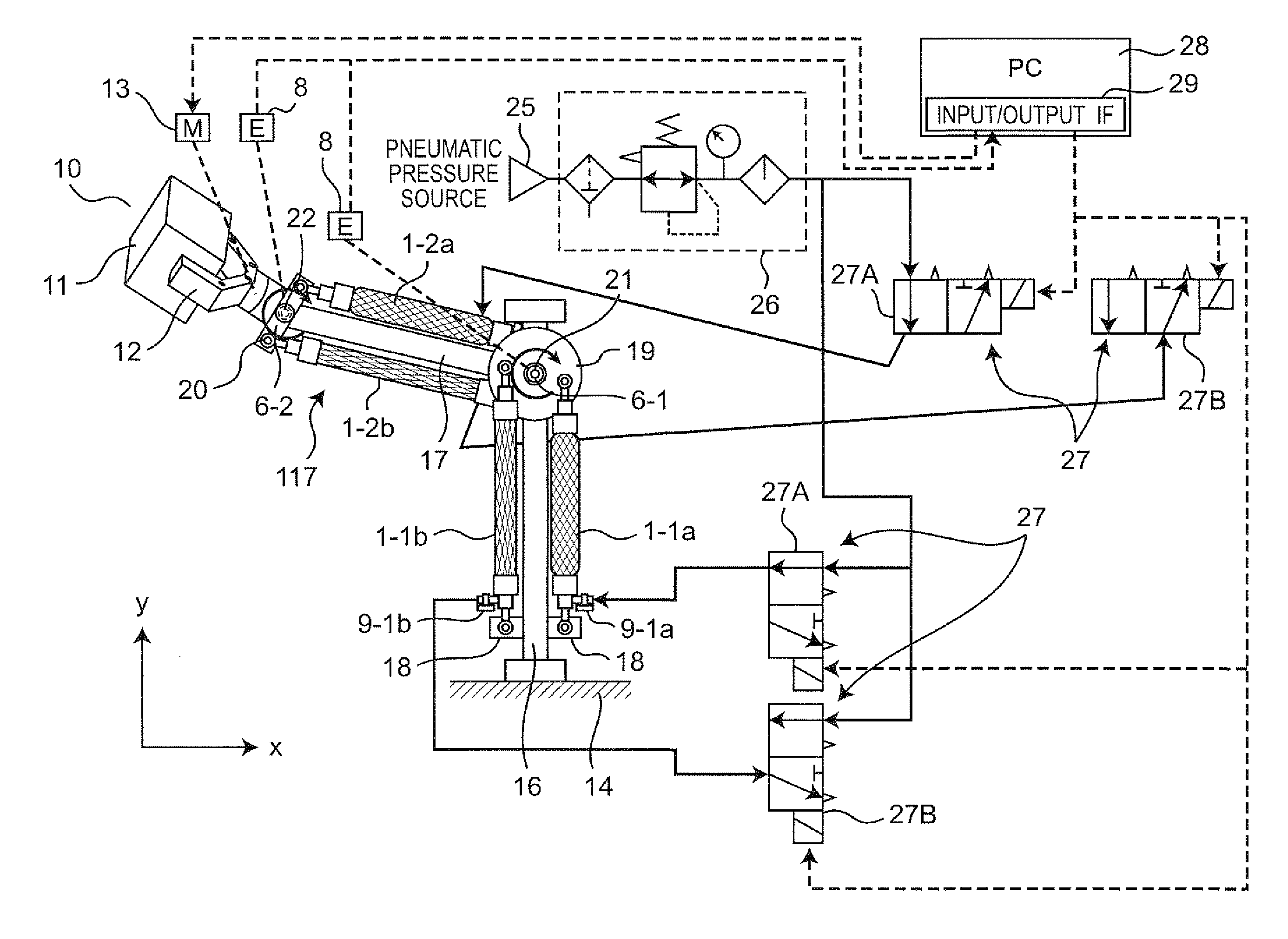
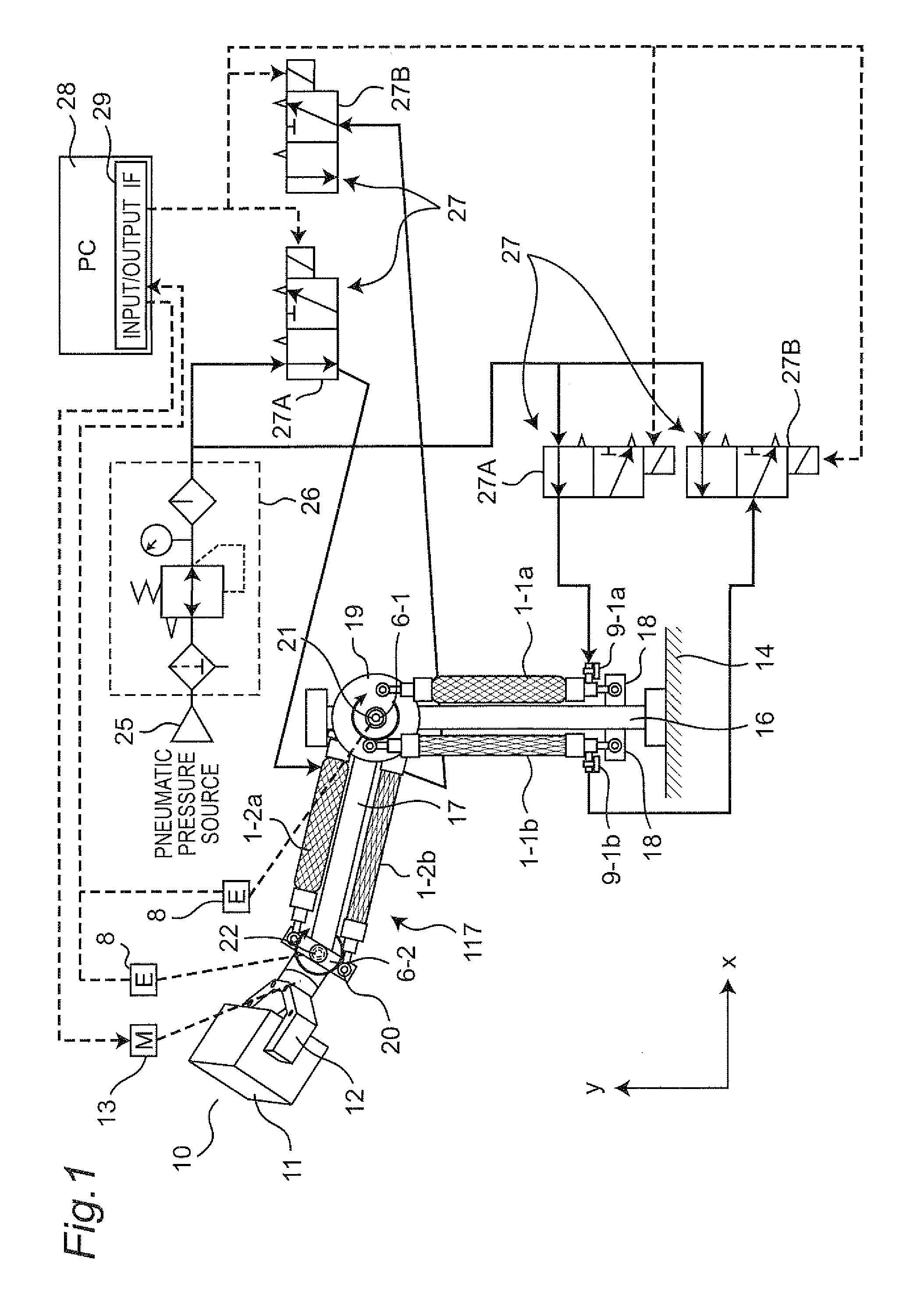
[0096]FIG. 1 is a view showing a configuration of the elastic actuator drive mechanism 10 according to the first embodiment of the present invention. The elastic actuator drive mechanism 10 is configured as a robot arm of two degrees of freedom, including a first joint shaft 6-1 and a second joint shaft 6-2. The first joint shaft 6-1 rotates positively and negatively within an xy plane inclusive of an x axis and a y axis provided perpendicularly to each other. The second joint shaft 6-2 also rotates positively and negatively within the xy plane. FIG. 1 illustrates elastic expansion / contraction structures 1-1a, 1-1b, 1-2a, and 1-2b, which are provided separately from one another as examples of elastic actuators or fluid pressure actuators. The elastic expansion / contraction structures will be denoted by reference sign...

second embodiment

[0189]Description is made to an example of specific configuration of a control apparatus 30 of an elastic actuator drive mechanism 10 according to a second embodiment of the present invention.

[0190]FIG. 16 is a view showing a specific configuration of an abnormal case operation control unit 33 according to the second embodiment of the present invention. The abnormal case operation control unit 33 includes a desired trajectory generation unit 40, an abnormal case torque control unit (a second desired internal state information calculation unit) 45B, a desired angular acceleration calculation unit 43, a pressure error calculation unit 46, a pressure error compensation unit 47, an angle estimation unit (as one example of an output estimation unit (output estimation unit)) 65, and an object grip signal output unit 48. The angle estimation unit (the output estimation unit) 65 and the abnormal case torque control unit (the second desired internal state information calculation unit) 45B, w...


PUM


Abstract

There is provided an abnormality determination unit that determines whether or not an output measurement unit is abnormal, in order to determine abnormality of the output measurement unit. When the output measurement unit is abnormal, the operation of an elastic actuator is controlled not in accordance with a measurement result of the output measurement unit but in accordance with an internal state model.

Description

CROSS-REFERENCE TO RELATED APPLICATIONS[0001]This is a continuation application of International Application No. PCT / JP2011 / 006818, filed Dec. 6, 2011, which claims priority of Japanese Patent Application No.: 2010-281167 filed on Dec. 17, 2010, the content of which is incorporated herein by reference.TECHNICAL FIELD[0002]The technical field relates to a control apparatus, a control method, and a control program for an elastic actuator drive mechanism, used for controlling operations of the drive mechanism that is driven by an elastic actuator such as a fluid pressure drive actuator, which is driven due to deformation of an elastic body.BACKGROUND ART[0003]In recent years, active development of robots cooperating with workers has been observed because of increase in cell production plants and the like. Unlike those conventional robots operating in areas separated from workers' areas, these robots cooperating with workers need to share the work areas with the workers. Accordingly, sp...

Claims


Application Information

Patent Timeline
IPC IPC(8): F01B19/04
CPCB25J9/1615B25J9/1674F15B11/16F15B2211/7052G05B23/0243G05B2219/39454G05B2219/39462B25J9/142F15B2211/7107
Inventor KOMATSU, MAYUMIOKAZAKI, YASUNAO
Owner PANASONIC CORP
Why Eureka
Try Eureka