Casing fill-up fluid management tool

a filling fluid and tool technology, applied in the direction of fluid removal, sealing/packing, borehole/well accessories, etc., can solve the problems of unfavorable spillage onto the drill floor of the drilling rig and/or elsewhere, displace air, accumulate or become trapped,

Active Publication Date: 2013-01-03
NOETIC TECH INC
View PDF3 Cites 24 Cited by
  • Summary
  • Abstract
  • Description
  • Claims
  • Application Information

AI Technical Summary

Benefits of technology

[0012]In accordance with one embodiment, the FMT incorporates a mud saver valve defining a mud saver flow path coincident with a medial region of the main body flow path. The mud saver valve is configured to prevent significant leakage flow from the flow line through the main body flow path, below a selected differential pressure in the downstream direction, while also allowing backflow into the upstream flow line at negligible cracking pressure (i.e., mud saver reopening pressure) in the upstream direction.

Problems solved by technology

Whenever a casing running tool (or “CRT”) is disengaged and removed from the casing after flowing liquids into a drill string or casing string, liquids such as drilling mud tend to drain from the tool bore, resulting in undesirable spillage onto the drill floor of the drilling rig and / or elsewhere.
Additionally, when a CRT is used to add liquids such as drilling mud or cement to a partially-filled casing string (i.e., casing fill-up and cementing operations, respectively), the liquid displaces air which through gravity separation tends to accumulate or become trapped at the upper end of the casing string below the CRT.
In situations where the CRT is in sealing engagement with the casing, this results in an increase of air pressure within the casing.
When the CRT is then removed from the upper end of the casing string, the pressurized air abruptly vents to atmosphere, which is typically undesirable even for relatively low levels of trapped pressure.
During cementing operations, the cement is frequently denser than the liquids being displaced, leading to conditions where the cement continues to fall within the wellbore after pumping is stopped, tending to induce suction pressure in the casing and hence to draw air into the casing, which may then interfere with subsequent fluid displacement operations.

Method used


Image

  • Casing fill-up fluid management tool
  • Casing fill-up fluid management tool
  • Casing fill-up fluid management tool

Examples


Embodiment Construction

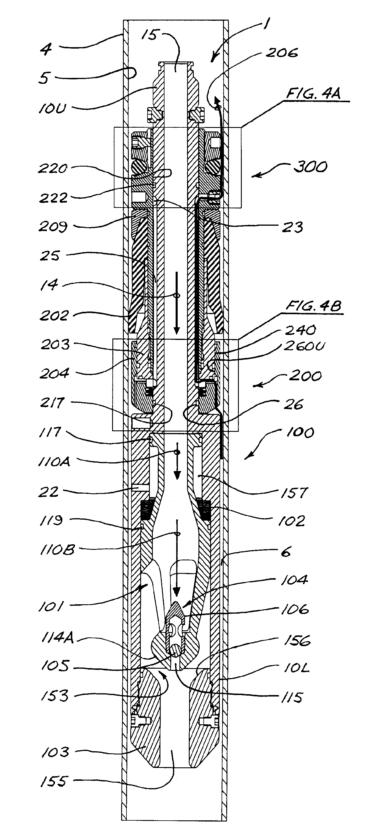
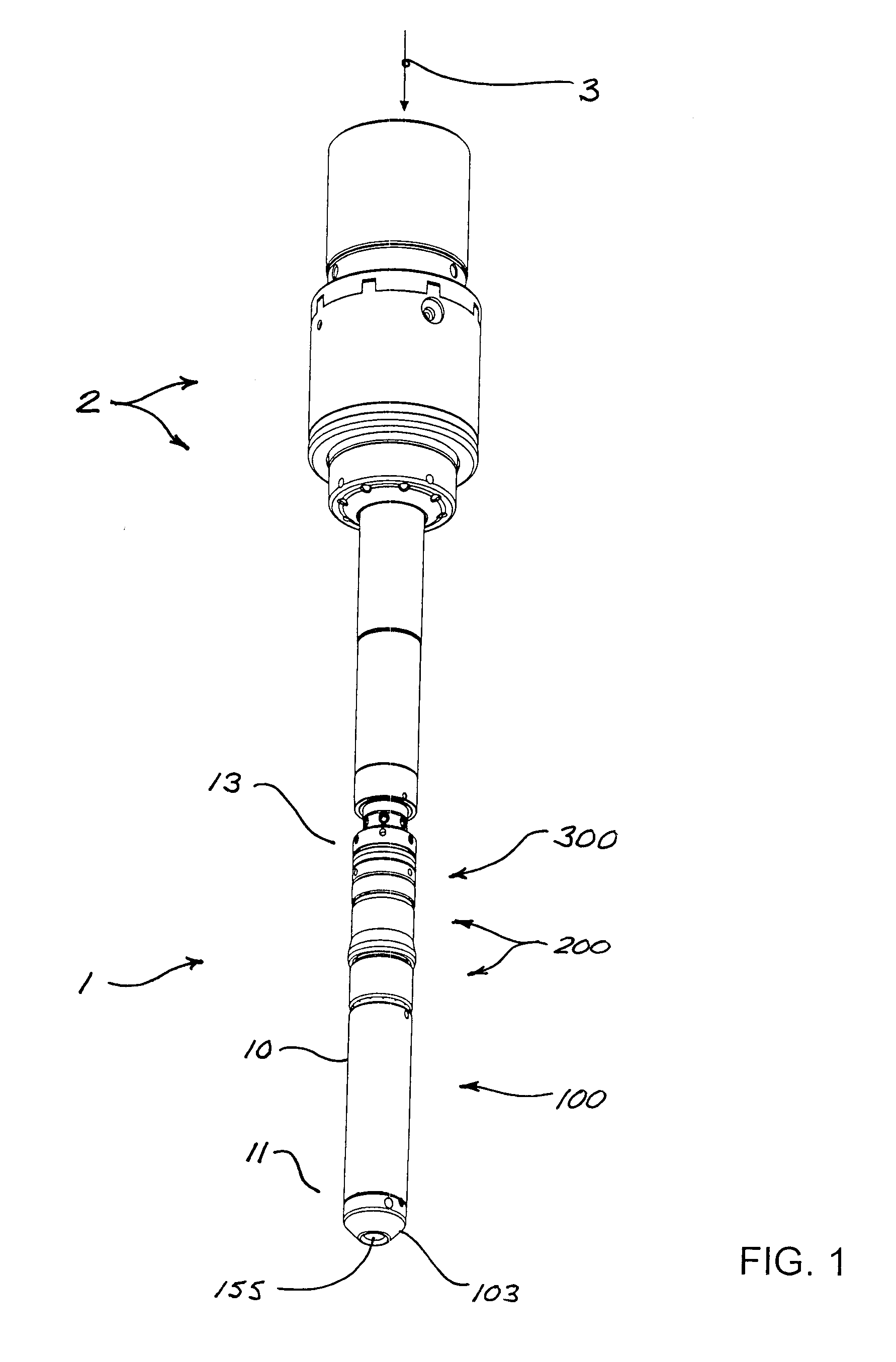
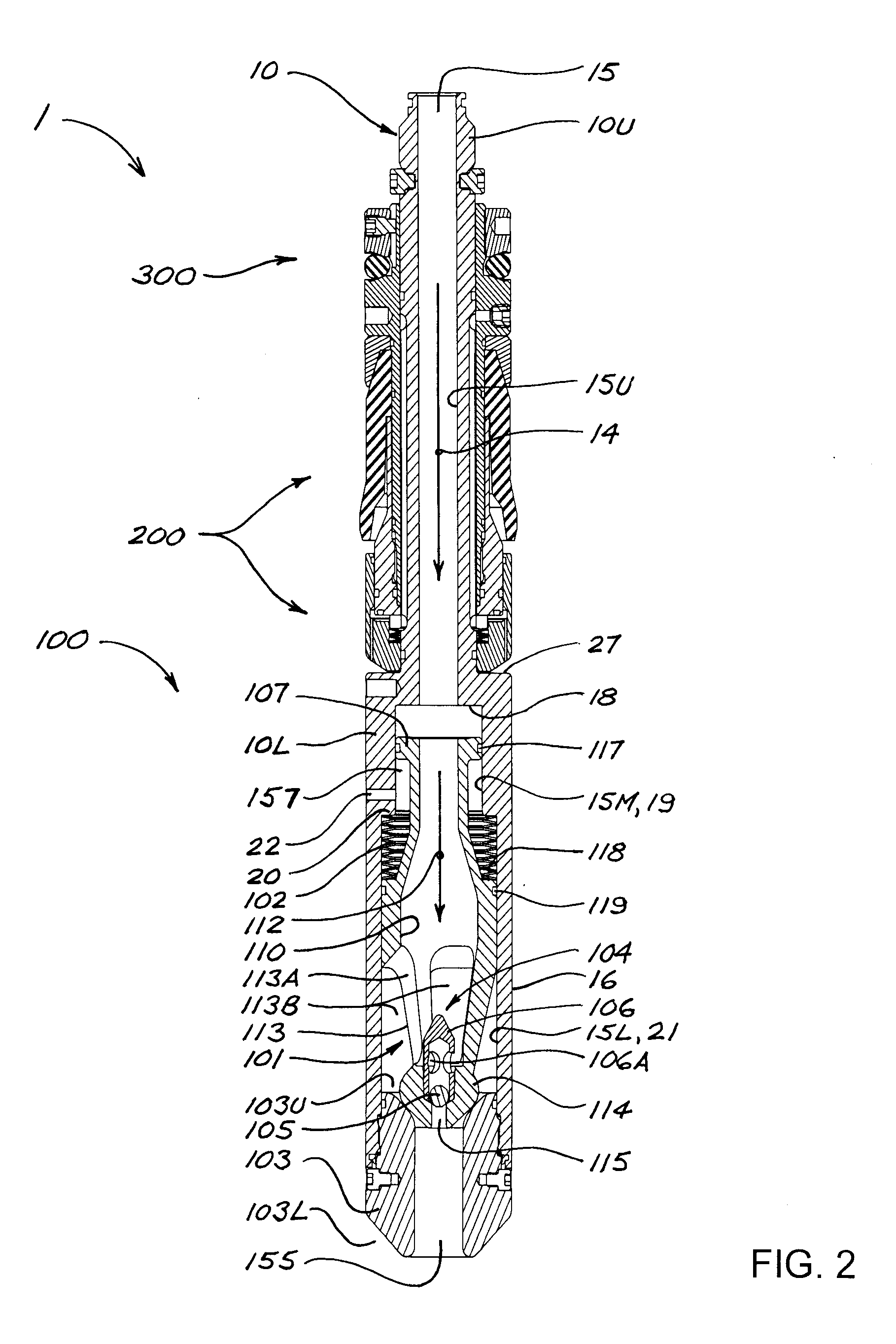
[0040]FIGS. 1 and 2 illustrate an embodiment of a fluid management tool (“FMT”) 1 in accordance with the present disclosure. FMT 1 has an upper end 13 and a lower end 11, and is shown in FIG. 1 with upper end 13 connected to the lower end of a casing running tool 2, and with an upstream flow line (represented by reference number 3) connected to casing running tool 2. As shown in cross-section in FIGS. 2 and 4 (and other Figures), FMT 1 comprises an elongate main body 10 having an upper section 10U and a lower section 10L. Main body 10 is of generally axi-symmetric configuration; i.e., symmetrical about a longitudinal axis. Lower section 10L of main body 10 has a wall 16 with an outer diameter greater than the outer diameter of upper section 10U. Although upper and lower sections 10U and 10L will preferably and most conveniently be of generally cylindrical configuration, upper and lower sections 10U and 10L or portions thereof could be of other configurations in alternative embodimen...


PUM


Abstract

A fluid management tool for introducing fluids into a casing string incorporates a mud saver valve configured to open and allow fluid flow in response to fluid flow pressure reaching a predetermined opening pressure, and will automatically close when fluid flow pressure is reduced to or below a predetermined closure pressure, thereby preventing fluid spillage when the tool is withdrawn from the casing. The mud saver valve includes a mud saver spool having a slotted spool cage and being axially movable within a longitudinal bore in the main body of the tool, between an upper or open position in which fluid can flow out of the spool cage and into a discharge bore at the lower end of the main body, and a lower or closed position in which the lower end is seated against the exit bore to prevent flow therethrough. A check valve may be incorporated into the lower end of the mud saver spool. The fluid management tool also may incorporate a main seal and air bleed valve subassembly and a secondary suction seal and check valve subassembly.

Description

FIELD[0001]The present disclosure relates in general to apparatus and methods for introducing fluids into a casing string or other tubular element during well construction operations, and for removing fluids from the casing string. In particular, the disclosure relates to apparatus and methods for introducing a fluid such as drilling mud or cement slurry into a casing string where the introduced fluid displaces air that must be vented from the casing.BACKGROUND[0002]Typical construction of an oil or gas well includes the operations of assembling a casing string, inserting the casing string into a wellbore, and cementing the casing in place in the wellbore. Casing assembly involves connecting multiple individual lengths of pipe (or “joints”) to form an elongate casing string. Threaded connections are usually used to join the individual lengths of pipe, requiring the application of torque to “make up” the connections, or to “break out” the connections should the string need to be disa...

Claims


Application Information

Patent Timeline
Patent Type & Authority Applications(United States)
IPC IPC(8): E21B21/10E21B34/06
CPCE21B21/10E21B21/103E21B33/16E21B33/12E21B34/06
Inventor SLACK, MAURICE WILLIAMALLEN, MATTHEW
Owner NOETIC TECH INC
Why Eureka
Try Eureka