

Calibration data selection device, method of selection, selection program, and three dimensional position measuring apparatus
- Summary
- Abstract
- Description
- Claims
- Application Information
AI Technical Summary
Benefits of technology
Problems solved by technology
Method used
Image

Examples
first embodiment
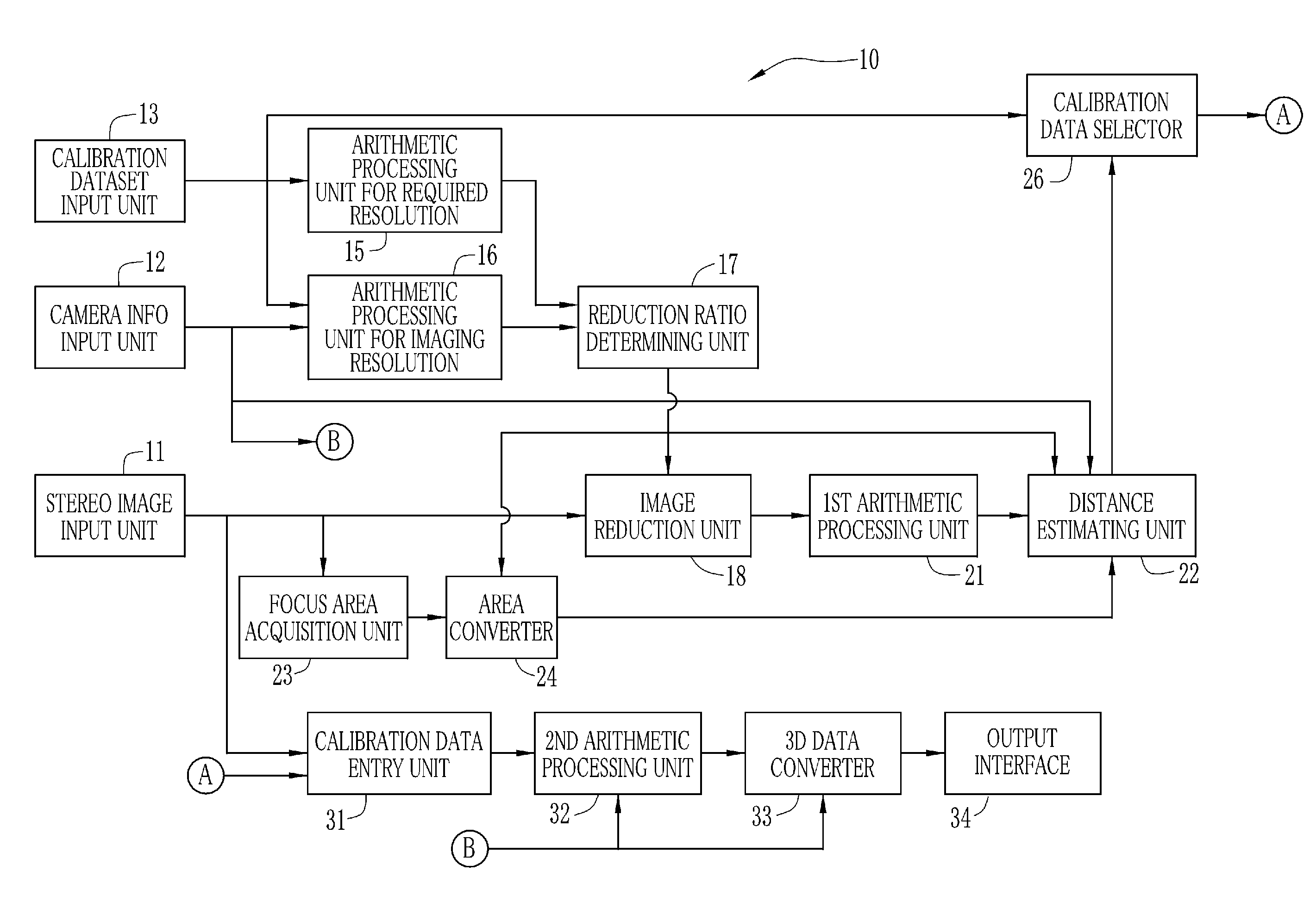
[0046]In FIG. 1, a three dimensional position measuring apparatus in which the present invention is embodied is shown. A three dimensional position measuring apparatus 10 measures three dimensional position information of a target object from a stereo image formed by photographing the target object with a stereo camera, or analyzes and retrieves coordinates (Xi, Yi, Zi) of a given point Pi on the target object in a three dimensional space. Before retrieving the position information, a task of processing is performed to estimate a distance of focusing (herein referred to as focusing distance) of taking optical systems at the time of photographing the target object. The stereo image is corrected according to calibration data for removing distortion of the taking optical systems according to the estimated focusing distance. The three dimensional position measuring apparatus 10 is constituted by, for example, a computer. Relevant elements are functioned by running a program in the compu...
second embodiment
[0093]A second embodiment is described, in which camera information is acquired from calibration data. Portions of the embodiment other than those described hereinafter are the same as the first embodiment. Substantially the same elements are designated with the same reference numerals, to omit further description.
[0094]In the embodiment as shown in FIG. 10, an arithmetic processing unit 51 for camera information is provided as a camera information acquisition unit instead of the camera information input unit. Respective calibration data are input by the calibration dataset input unit 13 to the arithmetic processing unit 51. The arithmetic processing unit 51 analyzes the calibration data, and retrieves and outputs camera information.
[0095]As shown in FIG. 11, the calibration data is expressed by a stereo parameter matrix which correlates a distortion parameter for expressing distortion of the taking optical systems to coordinates in the three dimensional space, and the pixel positio...
third embodiment
[0097]A third embodiment is described in correspondence with a stereo camera in which zoom lenses are used as taking optical systems. Portions of the embodiment other than those described hereinafter are the same as the first embodiment. Substantially the same elements are designated with the same reference numerals, to omit further description. In the third embodiment, a construction for photographing a stereo image is described in setting of the taking optical systems at one focal length of either of the wide-angle end and telephoto end. It is possible to apply the embodiment to other focal lengths, and to three or more focal lengths.
[0098]FIG. 12 shows a construction of the three dimensional position measuring apparatus 10 of the third embodiment. FIG. 13 shows steps of processing. The stereo image input unit 11 is supplied with a stereo image assigned with not only the focus area but a focal length of the taking optical systems used for photographing the stereo image as tag info...
PUM
 Abstract
Description
Claims
Application Information