
Key management system, communication device and key sharing method

Active Publication Date: 2021-04-15
MITSUBISHI ELECTRIC CORP
View PDF1 Cites 3 Cited by
  • Summary
  • Abstract
  • Description
  • Claims
  • Application Information

AI Technical Summary

Benefits of technology

The invention allows for a communication device in a vehicle to share keys with multiple other devices in the vehicle without exchanging many communication packets. This reduces processing time and makes the key sharing process faster.

Problems solved by technology

However, since automobiles are manufactured by assembling in-vehicle devices made by various manufacturers, it is difficult for each manufacturer to grasp communication relationship of the in-vehicle devices in advance, and it is difficult to set a key to the in-vehicle device when manufacturing the in-vehicle device.
In addition, since the in-vehicle device may be replaced during operation, it is not sufficient to set the key to the in-vehicle device at the time of manufacture.
However, since there are cost and resource limitations in the in-vehicle device, it is inevitable that there is the in-vehicle device that does not support public key cryptography.
Therefore, it is difficult to apply the method according to Patent Literature 1 to all the in-vehicle devices.

Method used


Image

  • Key management system, communication device and key sharing method
  • Key management system, communication device and key sharing method
  • Key management system, communication device and key sharing method

Examples


embodiment 1

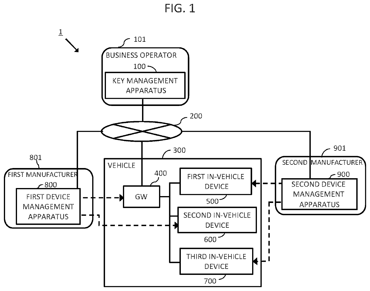
[0089]FIG. 1 is a schematic diagram showing an entire configuration of a key sharing system according to Embodiment 1 of the present invention.

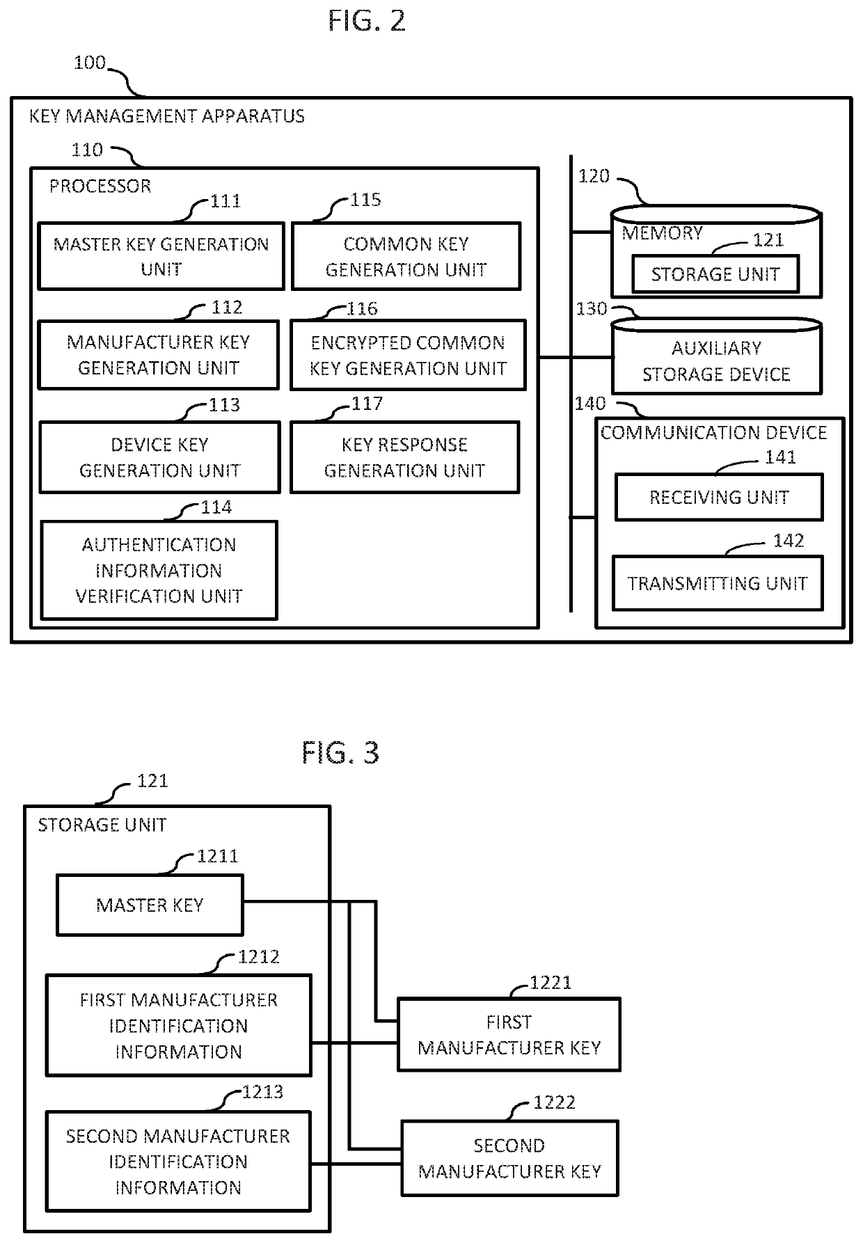
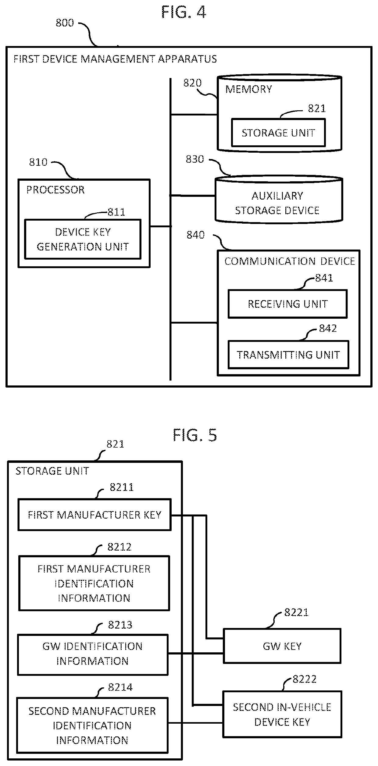
[0090]In the figure, a key sharing system 1 includes a business operator 101 provided with a key management apparatus 100, a vehicle 300 equipped with a plurality of in-vehicle devices to be authenticated, a first manufacturer 801 provided with a first device management apparatus 800, and a second manufacturer 901 provided with a second device management apparatus 900, and the key management apparatus 100, a GW 400, the first device management apparatus 800, and the second device management apparatus 900 are set to communicate with each other via a network 200.

[0091]Here, the business operator 101 has an equipment serving as a master station including the key management apparatus 100, and is also a manufacturer that manufactures the vehicle 300 serving as a slave station communicating with the master station. Although the figure shows the veh...

embodiment 2

[0302]In Embodiment 1 described above, the GW 400 is configured to share keys simultaneously for all the in-vehicle devices present in the vehicle 300. However, when a network in the vehicle 300 is divided into units called domains, and each in-vehicle device is configured to belong to one of the domains depending on its function, the key sharing process may be performed on a domain basis, and such an embodiment is shown in FIG. 30. The domains include, for example, a body system, an information system, and a power system.

[0303]In FIG. 30, the vehicle 300 includes the GW 400, the first in-vehicle device 500, the second in-vehicle device 600, the third in-vehicle device 700, a fourth in-vehicle device 330, a fifth in-vehicle device 340, and a sixth in-vehicle device 350, and is divided into a domain A310 including the first in-vehicle device 500, the second in-vehicle device 600, and the third in-vehicle device 700, and a domain B320 including the fourth in-vehicle device 330, the fi...


PUM


Abstract

A key management apparatus receives a key request including a first device identification information and a second device identification information, encrypts a common key using the first device identification information to generate a first encrypted common key, encrypts the common key using the second device identification information to generate a second encrypted common key, and transmits a key response including the first encrypted common key and the second encrypted common key. A first device receives the key response, decrypts the first encrypted common key using the first device identification information to obtain the common key, and transmits the second encrypted common key. A second device receives the second encrypted common key and decrypts the second encrypted common key using the second device identification information to obtain the common key.

Description

TECHNICAL FIELD[0001]The present invention relates to a key management technology for establishing secure communication.BACKGROUND ART[0002]At present, in the automobile industry, various driving support functions such as an automatic braking function and a lane keeping function are being developed to realize autonomous driving in the 2020s. These developed driving support functions are realized in automobiles.[0003]From now on, it is expected that more advanced driving support functions will be realized by communicating with various external things such as a cloud, a roadside device and another vehicle.[0004]On the other hand, when the vehicle communicates with the outside, a possibility of the vehicle being subjected to malicious attack is increased, and it is important to establishing secure communication.[0005]As a technology related to such communication security, a method for performing authentication has been proposed. (See Non-Patent Literature 1). In this method, it is assu...

Claims


Application Information

Patent Timeline
IPC IPC(8): H04L9/08H04L9/32H04L29/08
CPCH04L9/083H04L9/0866H04L63/0869H04L9/0822H04L67/12H04L9/3271H04W4/40H04L2463/062H04L63/062H04L63/0435H04L2209/84G06F21/445H04W12/037H04W12/0431
Inventor TANJI, MASAMICHIITOI, MAKOTOKOBAYASHI, NOBUHIROYAMAGUCHI, TERUYOSHI
Owner MITSUBISHI ELECTRIC CORP
Learn More