Cooling system for light emitting device and light emitting device using the same
- Summary
- Abstract
- Description
- Claims
- Application Information
AI Technical Summary
Benefits of technology
Problems solved by technology
Method used
Image

Examples
first embodiment
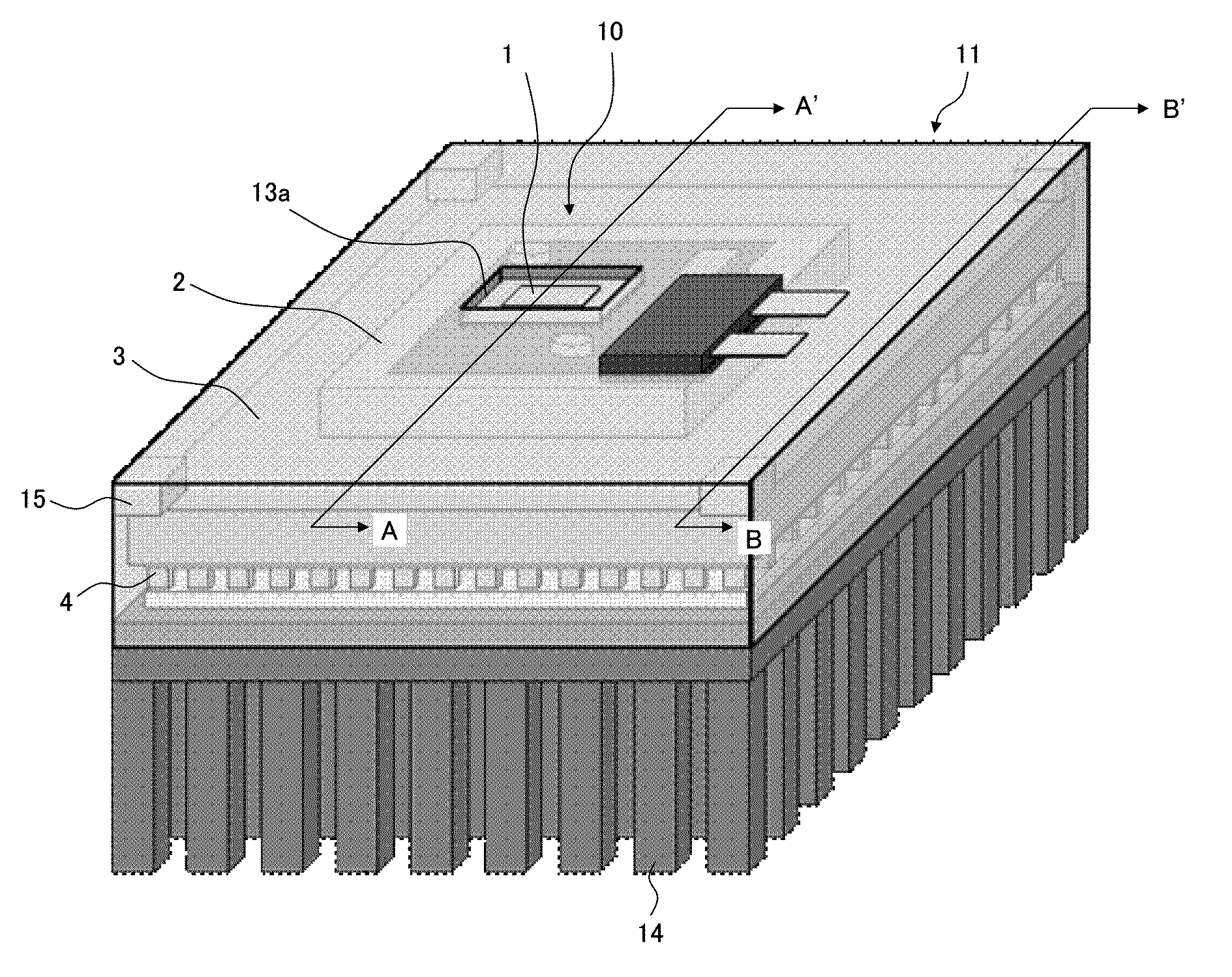
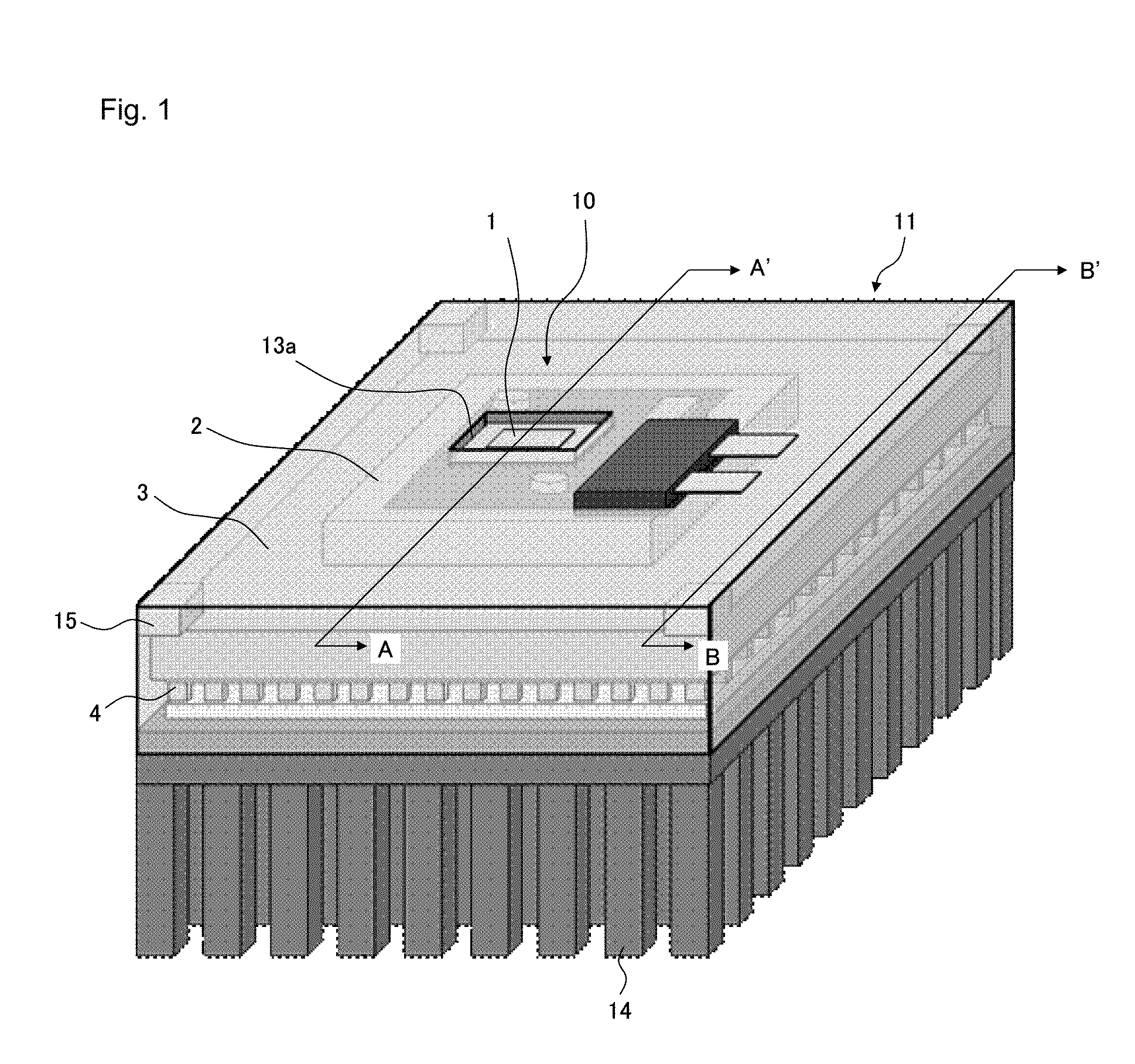
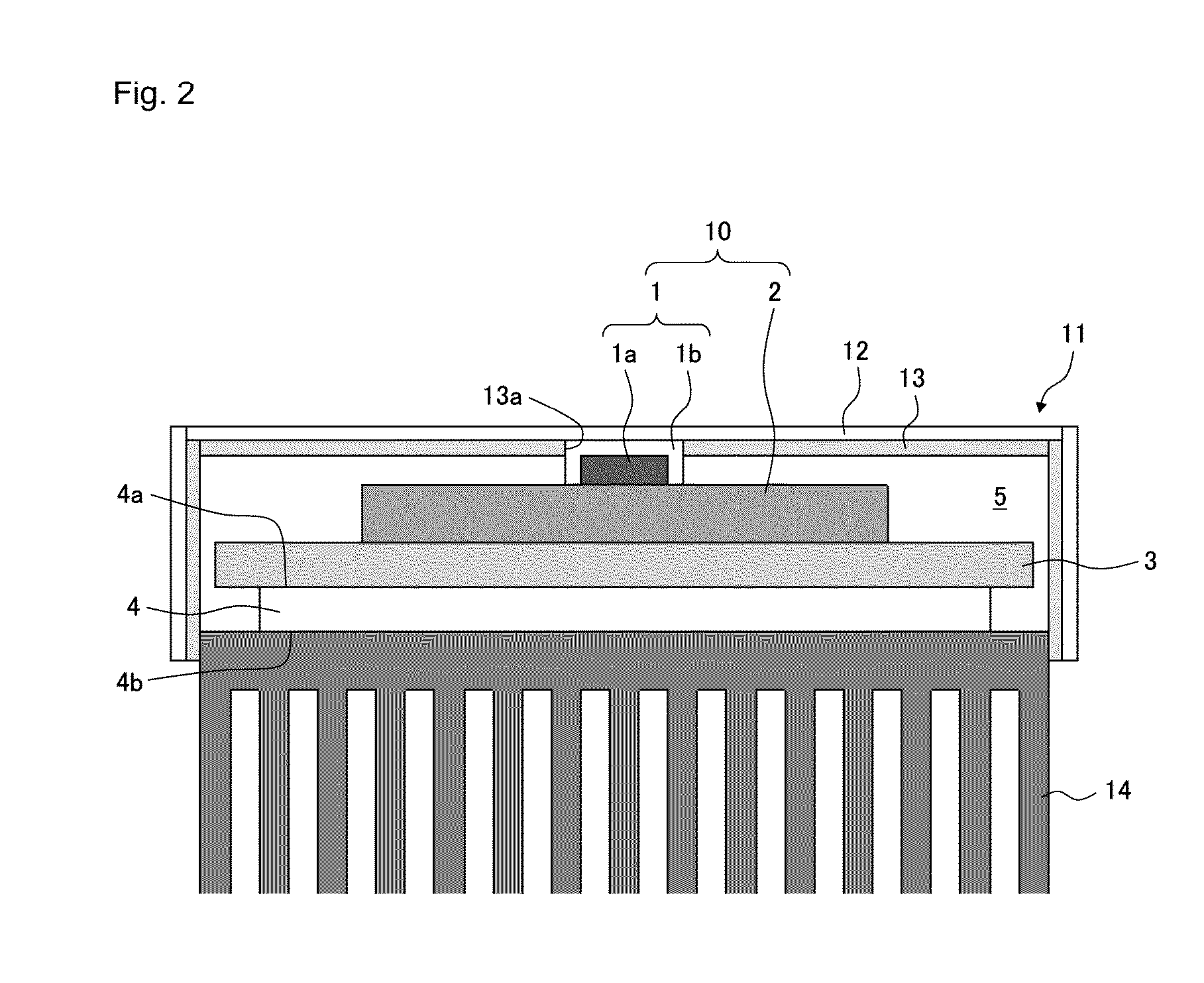
[0018]First, referring to FIGS. 1 to 3, the cooling system of a light emitting device according to a first embodiment of the present invention will be described.
[0019]FIG. 1 is a perspective view schematically showing a light emitting device using the cooling system according to this embodiment. FIG. 2 is a schematic sectional view along the line A-A′ shown in FIG. 1, and FIG. 3 is a schematic sectional view along the line B-B′ shown in FIG. 1.
[0020]In the cooling system of this embodiment, as shown in FIGS. 1 and 2, as a cooling element for cooling light emitting device 10 including light emitting body 1, Peltier element 4, namely, a thermoelectric element utilizing the Peltier effect, is used. Light emitting body 1 to be cooled is LED element 1a around which protection member 1b made of glass is placed. LED element 1a is mounted on LED substrate 2 made of metal.
[0021]The cooling system of this embodiment includes Peltier element 4, heat sink (heat dissipation member) 14 disposed i...
second embodiment
[0034]Next, a cooling system for a light emitting device according to a second embodiment of the present invention will be described.
[0035]FIG. 4 is a sectional view schematically showing a light emitting device using the cooling system according to this embodiment, corresponding to FIG. 2.
[0036]The cooling system of this embodiment is a modified example of the first embodiment where the configuration of members defining hermetically sealed space 5 is changed. In this embodiment, in place of cover film 11 and heat sink 14 of the first embodiment, cover member 21 and water-cooling cold plate 24 are provided. Other components are similar to those of the first embodiment, and effects provided by this embodiment are also similar to those of the first embodiment. Hereinafter, members similar to those of the first embodiment are denoted by similar reference numerals, and description thereof will be omitted.
[0037]Cold plate 24 integrated with metal fixed plate 25 is disposed in contact wit...
third embodiment
[0041]FIG. 5 is a sectional view schematically showing a light emitting device using a cooling system according to a third embodiment of the present invention, corresponding to FIG. 2.
[0042]This embodiment is a modified example of the second embodiment where ring member 37 is added to surround light emitting body 1. Ring member 37 is fixed onto LED substrate 2 that is in contact with light emitting body 1. In this embodiment, the opening edge of exit opening 21a is secured to the upper surface of ring member 37 by an adhesive or the like, thereby forming hermetically sealed space 5. Preferably, in the above-described mechanism for preventing the occurrence of dew condensation, to improve heat conduction between light emitting body 1 and cover member 12, ring member 37 is made of a heat-conductive resin or a metal.
[0043]In place of cover member 21 of this embodiment, the cover film of the first embodiment where the openings are formed not only in the metal film but also in the resin ...
PUM
 Abstract
Description
Claims
Application Information
 - Generate Ideas
- Intellectual Property
- Life Sciences
- Materials
- Tech Scout
- Unparalleled Data Quality
- Higher Quality Content
- 60% Fewer Hallucinations
Browse by: Latest US Patents, China's latest patents, Technical Efficacy Thesaurus, Application Domain, Technology Topic, Popular Technical Reports.
© 2025 PatSnap. All rights reserved.Legal|Privacy policy|Modern Slavery Act Transparency Statement|Sitemap|About US| Contact US: help@patsnap.com