Power supply device and vehicle including the same

a technology of power supply device and battery cell, which is applied in the direction of cell components, electrochemical generators, cell component details, etc., can solve the problems of bringing the cooled part to the dew point, condensation on the surface of the battery cell, and unintentional flow of electric current, so as to prevent the condensation of moisture in the air

Inactive Publication Date: 2013-01-03
SANYO ELECTRIC CO LTD
View PDF1 Cites 68 Cited by
  • Summary
  • Abstract
  • Description
  • Claims
  • Application Information

AI Technical Summary

Benefits of technology

[0010]To achieve the above object, a power supply device according to a first aspect of the present invention includes a battery assembly 5, a cover case 16, a cooling plate 61, and a sealing member 20. The battery assembly 5 includes a plurality of rectangular battery cells which are arranged side by side. The cover case 16 has a box shape having one opened surface with opening. The battery assembly 5 is covered with surfaces of the cover case 16 other than the opening. The cooling plate 61 closes the one opened surface of the covering case 16, and i...

Problems solved by technology

On the other hand, high cooling performance will bring cooled part to relatively low temperature, and may bring the cooled part to the dew point.
As a result, moisture in air is cooled, which in turn may cause condensation on surfaces of the battery cells.
If condensation occurs, electric current may unintentionally flow, or the condensation may cause corrosion.
However, if the peripheral parts of battery cells are completely covered by resin, it will be difficult to thermally couple the battery cells ...

Method used


Image

  • Power supply device and vehicle including the same
  • Power supply device and vehicle including the same
  • Power supply device and vehicle including the same

Examples


first embodiment

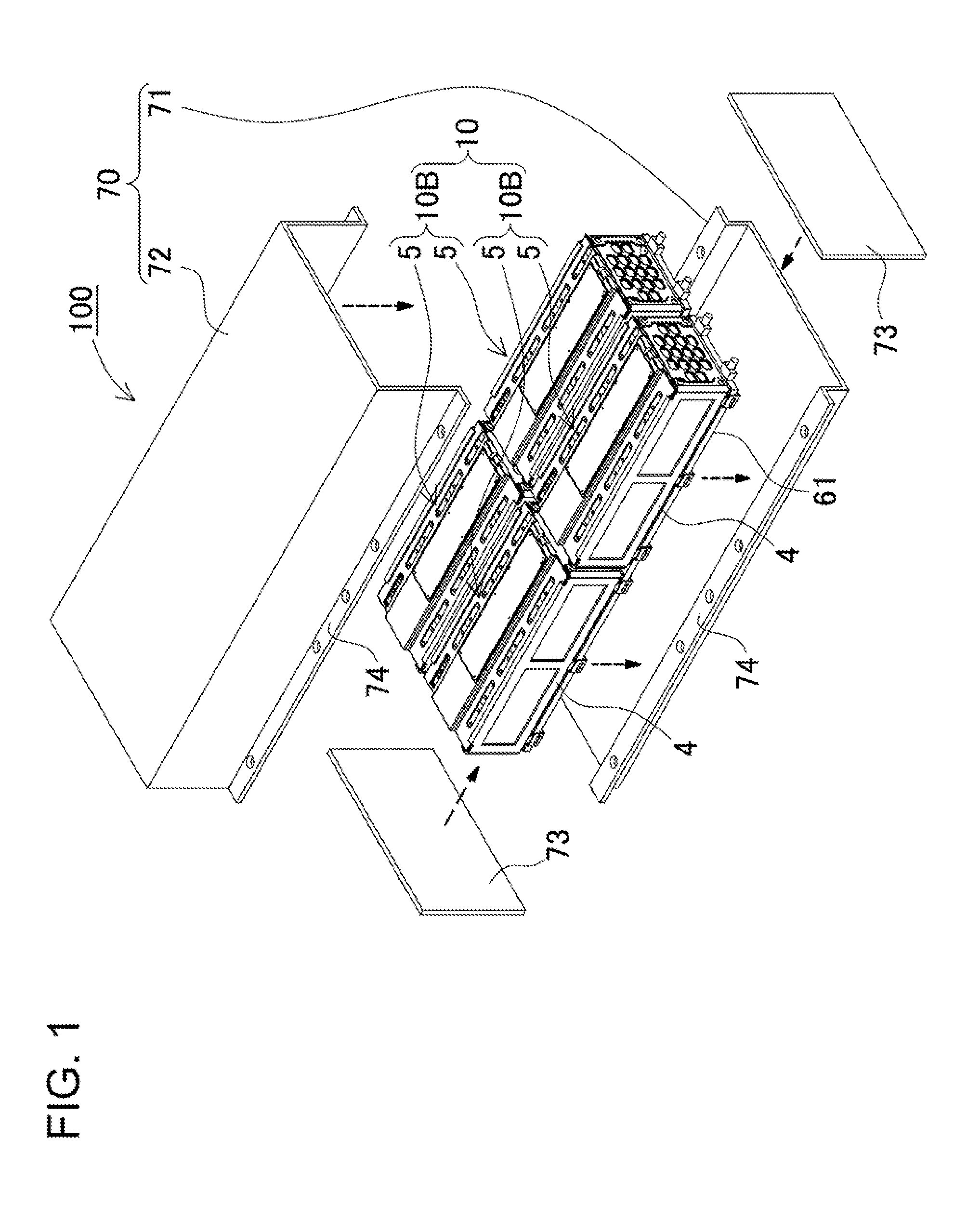
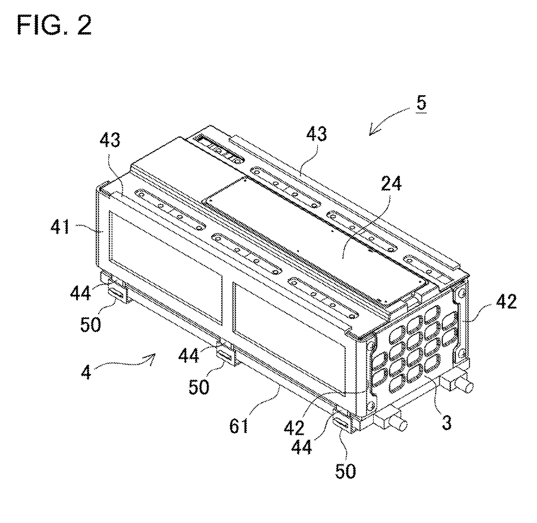
[0054]The following description will describe a power supply device 100 according to a first embodiment of the present invention with reference to FIGS. 1 to 13. In this embodiment, the present invention is applied to a vehicle power supply device. FIG. 1 is an exploded perspective view showing a power supply device 100. FIG. 2 is a perspective view showing a battery assembly 5 shown in FIG. 1. FIG. 3 is an exploded perspective view showing the battery assembly 5 shown in FIG. 2 with a cooling plate 61 being removed from the battery assembly 5. FIG. 4 is a perspective view showing the battery assembly 5 shown in FIG. 2 as viewed from the lower side. FIG. 5 is an exploded perspective view showing the battery assembly 5 shown in FIG. 2. FIG. 6 is an exploded perspective view showing the battery assembly 5 shown in FIG. 5. FIG. 7 is a cross-sectional view showing a power supply device according to a modified embodiment. FIG. 8 is a schematic cross-sectional view showing an exemplary po...

second embodiment

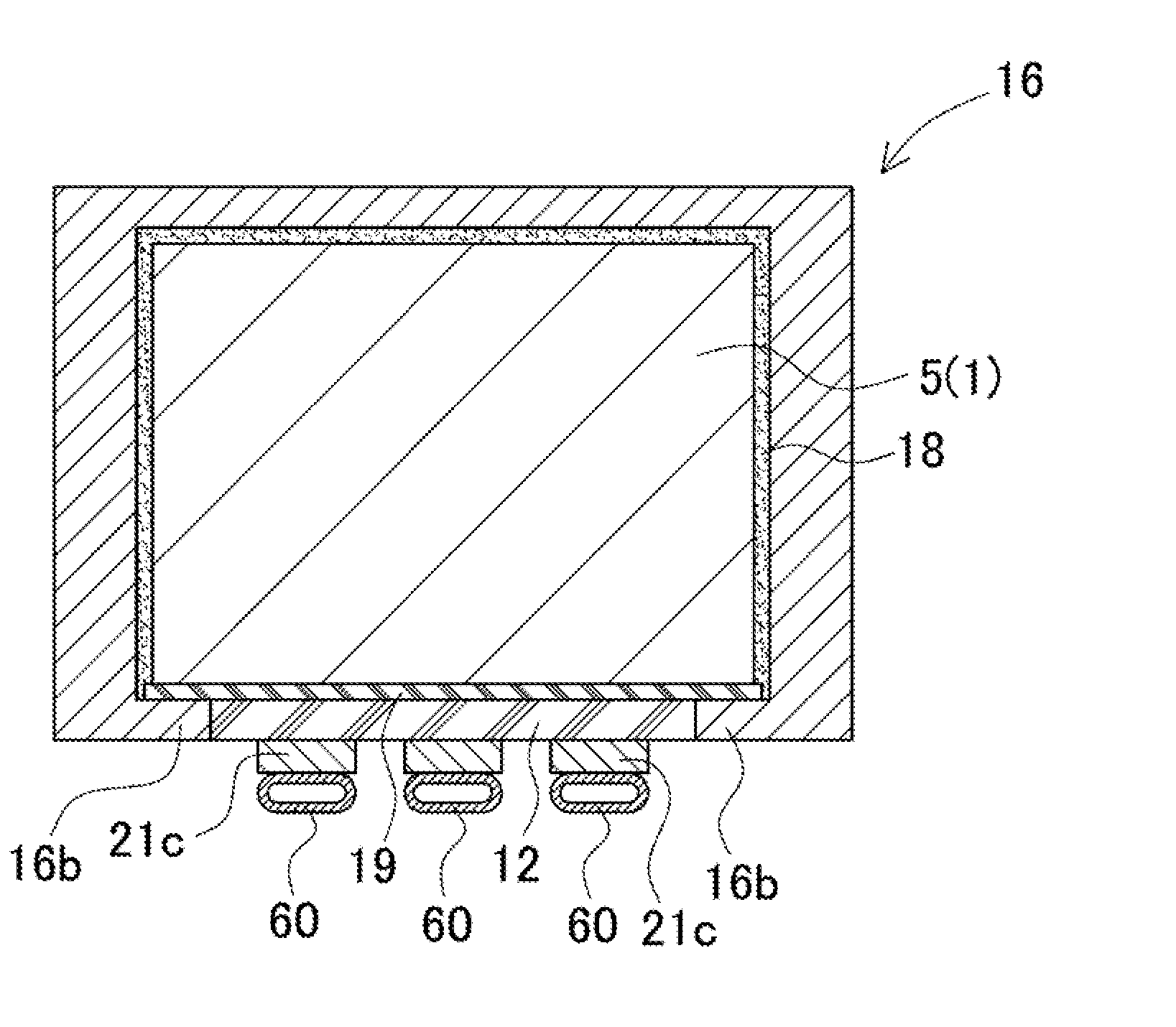
[0083]As discussed above, the battery assembly 5 can be airtightly closed by the cover case and the cooling plate whereby preventing air from flowing into the cover case. Therefore, it is possible to prevent the moisture in air from condensing in the cover case. In addition to the waterproof structure which prevents the entry of water from the surface side into the interior side of the cover case, in order to protect the surfaces of the battery assembly accommodated in the cover case against water droplets, and the like, a sealing layer can cover the surfaces of the battery assembly so that gaps between the battery assembly and the cover case can be filled with the sealing layer. FIG. 14 is a cross-sectional view showing a power supply device according to a second embodiment to which this feature is adopted. In this illustrated power supply device, a sealing layer 18 is arranged between the battery assembly 5 and the cover case 16. That is, gaps between the battery assembly 5 and th...

third embodiment

[0090]The waterproof sheet 19 can be partially cut out so that the thermally conductive sheet 12 is partially brought into direct contact with the battery assembly 5. FIG. 15 shows this type of power supply device according to a third embodiment. In this illustrated battery assembly 5, after the sealing material is cured, the waterproof sheet 19 for covering the bottom surface of the battery assembly 5 is partially cut out and is removed shown in FIG. 17. A part of the bottom surface of the battery assembly 5 is exposed correspondingly to the removed part of the waterproof sheet 19. The thermally conductive sheet 12 is pressed onto this exposed surface so that the thermally conductive sheet 12 is brought into direct intimate contact with the battery assembly 5 whereby reducing thermal resistance. As a result, it is expected that the cooling effect by the cooling plate 61 can be improved. After the sealing material is cured, the surface of the battery assembly 5 has been sealed excep...


PUM


Abstract

A power supply device includes a battery assembly, a box-shaped cover case, a cooling plate, and a waterproof sheet. The battery assembly includes rectangular battery cells arranged side by side. The cover case has an opening. Exterior surfaces of the battery assembly are covered with surfaces of the cover case other than the opening. The cooling plate is thermally coupled to one surface of the battery assembly through the opening. Coolant flows through the cooling plate whereby transferring heat from the battery assembly to the coolant. The waterproof sheet covers the one surface of the battery assembly. Gaps between the battery assembly and the cover case are filled with a sealing material so that a sealing layer is interposed between them. The waterproof sheet is fastened by the sealing layer.

Description

BACKGROUND OF THE INVENTION[0001]1. Field of the Invention[0002]The present invention mainly relates to a power supply device which can be used as large current power supplies for electric motor for driving cars such as hybrid car and electric vehicle, and as electric power storages for home use and manufacturing plants. The present invention also relates to a vehicle including this power supply device.[0003]2. Description of the Related Art[0004]Power supply devices such as battery packs for vehicles are required which can provide high output electric power. A number of battery cells are serially connected to each other to increase the output voltage whereby increasing the output electric power of a power supply device. Battery cells generate heat when charged / discharged with a large current. The heat amount generated by battery cells increases with the number of the battery cells. For this reason, heat dissipating mechanisms are required which can efficiently thermally conduct and...

Claims


Application Information

Patent Timeline
IPC IPC(8): H01M10/50H01M2/04H01M2/10H01M10/60H01M10/613H01M10/625H01M10/627H01M10/653H01M10/6556H01M10/6567H01M50/209H01M50/262H01M50/271H01M50/289
CPCH01M2/1072H01M2/1094H01M10/5004H01M10/5075H01M10/5032H01M10/5053H01M10/5057H01M10/5016H01M10/625H01M10/647H01M10/6556H01M10/6567H01M10/6554H01M10/613Y02E60/10H01M50/24H01M50/209H01M50/289H01M50/262H01M50/271
Inventor HASHIMOTO, HIROYUKITSUCHIYA, MASAKIASAI, YASUHIROSETO, TAKASHIKOMORIYA, TAKAHIDE
Owner SANYO ELECTRIC CO LTD
Why Eureka
Try Eureka