Antenna, dielectric window, plasma processing apparatus and plasma processing method

Active Publication Date: 2013-01-10
TOKYO ELECTRON LTD
View PDF12 Cites 211 Cited by
  • Summary
  • Abstract
  • Description
  • Claims
  • Application Information

AI Technical Summary

Benefits of technology

[0025]In accordance with the illustrative embodiment, uniformity of the substr

Problems solved by technology

For example, in the etching apparatus using the radial line slot antenna described in Patent Document

Method used


Image

  • Antenna, dielectric window, plasma processing apparatus and plasma processing method
  • Antenna, dielectric window, plasma processing apparatus and plasma processing method
  • Antenna, dielectric window, plasma processing apparatus and plasma processing method

Examples


Embodiment Construction

[0043]Hereinafter, illustrative embodiments will be described in detail with reference to the accompanying drawings. Through the specification and the drawings, parts having substantially the same functions and configurations will be assigned same reference numerals.

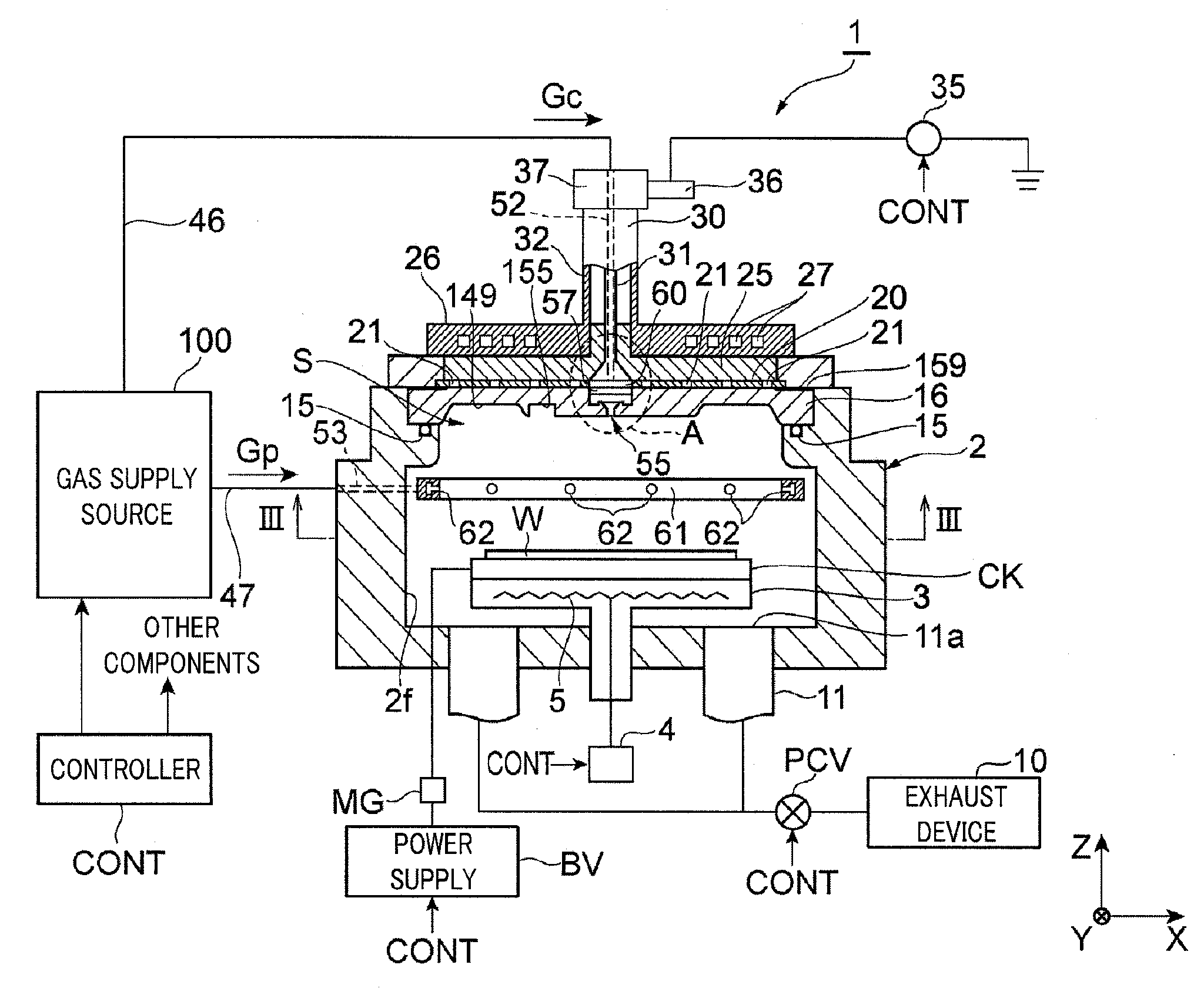
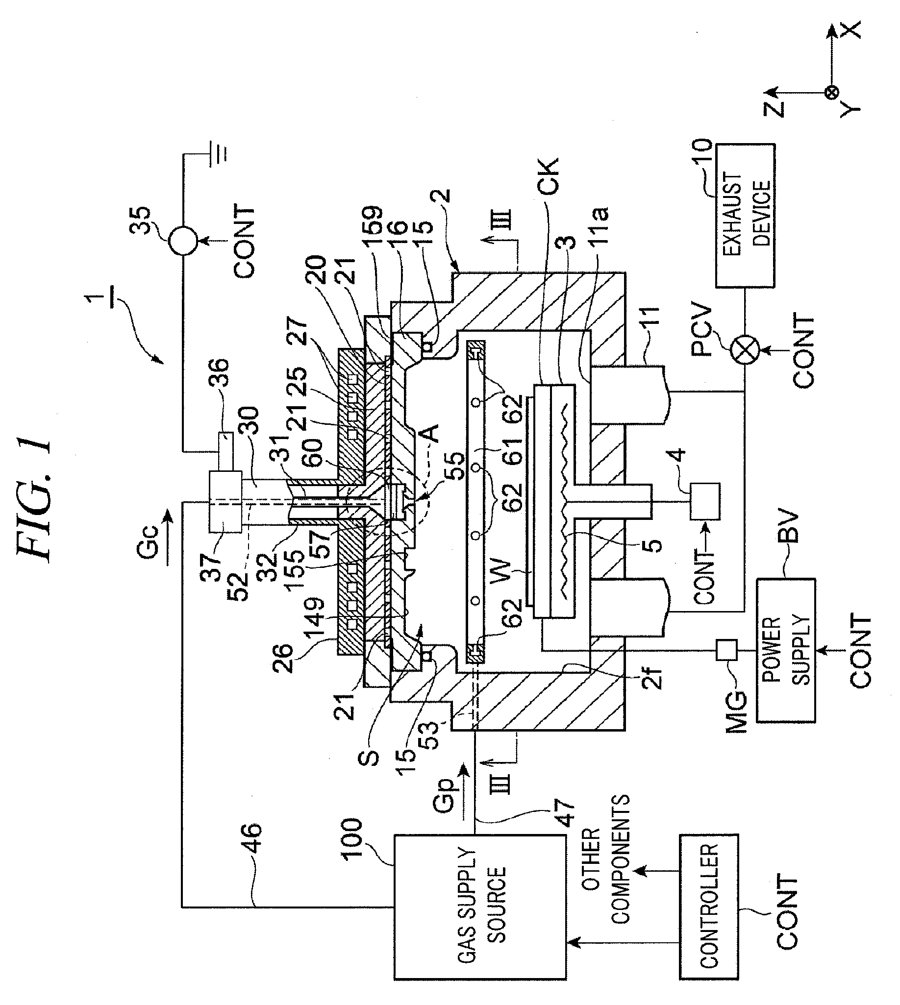
[0044]FIG. 1 is a longitudinal cross sectional view of a plasma processing apparatus in accordance with an illustrative embodiment.

[0045]The plasma processing apparatus 1 includes a cylindrical processing chamber 2. A ceiling of the processing chamber 2 is covered by a dielectric window (ceiling plate) 16 made of a dielectric material. The processing chamber 2 is made of, but not limited to, aluminum and is electrically grounded. An inner wall surface of the processing chamber 2 is coated with an insulating protective film 2f such as alumina.

[0046]A table 3 for mounting thereon a semiconductor wafer W (hereinafter, simply referred to as a “wafer”) as a substrate is provided at the center of the bottom of the processing c...


PUM

PropertyMeasurementUnit
Thicknessaaaaaaaaaa
Dielectric polarization enthalpyaaaaaaaaaa
Shapeaaaaaaaaaa

Abstract

An antenna, a dielectric window, a plasma processing apparatus and a plasma processing method are capable of improving uniformity of a substrate surface processing amount in the surface of the substrate. The antenna includes the dielectric window 16; and a slot plate 20, provided on one side of the dielectric window 16, having a plurality of slots 133. The dielectric window 16 has a flat surface 146 surrounded by a ring-shaped first recess; and a plurality of second recesses 153 formed on the flat surface 146 so as to surround a center of the flat surface 146. Here, the flat surface 146 is formed on the other side of the dielectric window 16. When viewed from a thickness direction of the slot plate, a center of each second recess 153 is located within each slot 133 of the slot plate.

Description

CROSS-REFERENCE TO RELATED APPLICATION[0001]This application claims the benefit of Japanese Patent Application No. 2011-150365 filed on Jul. 6, 2011, the disclosures of which are incorporated herein by reference.FIELD OF THE INVENTION[0002]The present disclosure relates to an antenna, a dielectric window, a plasma processing apparatus and a plasma processing method for use in processing a substrate by plasma excited from a processing gas introduced into a processing chamber.BACKGROUND OF THE INVENTION[0003]Conventionally, a plasma processing apparatus has been used in various fields. Patent Document 1 describes a plasma etching apparatus using parallel plates for generating plasma.[0004]Recently, there has been developed a plasma etching apparatus using a radial line slot antenna for generating plasma (Patent Document 2). In the plasma processing apparatus using the radial line slot antenna, a slot antenna having a multiple number of slots is disposed on a dielectric window of a pro...

Claims


Application Information

Patent Timeline
IPC IPC(8): H01Q13/10B05C11/00
CPCH01J37/32238H01J37/3222H01J37/32229H01J37/3244
Inventor MATSUMOTO, NAOKIYOSHIKAWA, WATARUYOSHIKAWA, JUNMOYAMA, KAZUKIISHIBASHI, KIYOTAKAMORITA, OSAMUTANIKAWA, TAKEHIRO
Owner TOKYO ELECTRON LTD
Why Eureka
Try Eureka