

Orbital Welding Apparatus
- Summary
- Abstract
- Description
- Claims
- Application Information
AI Technical Summary
Benefits of technology
Problems solved by technology
Method used
Image

Examples
Embodiment Construction
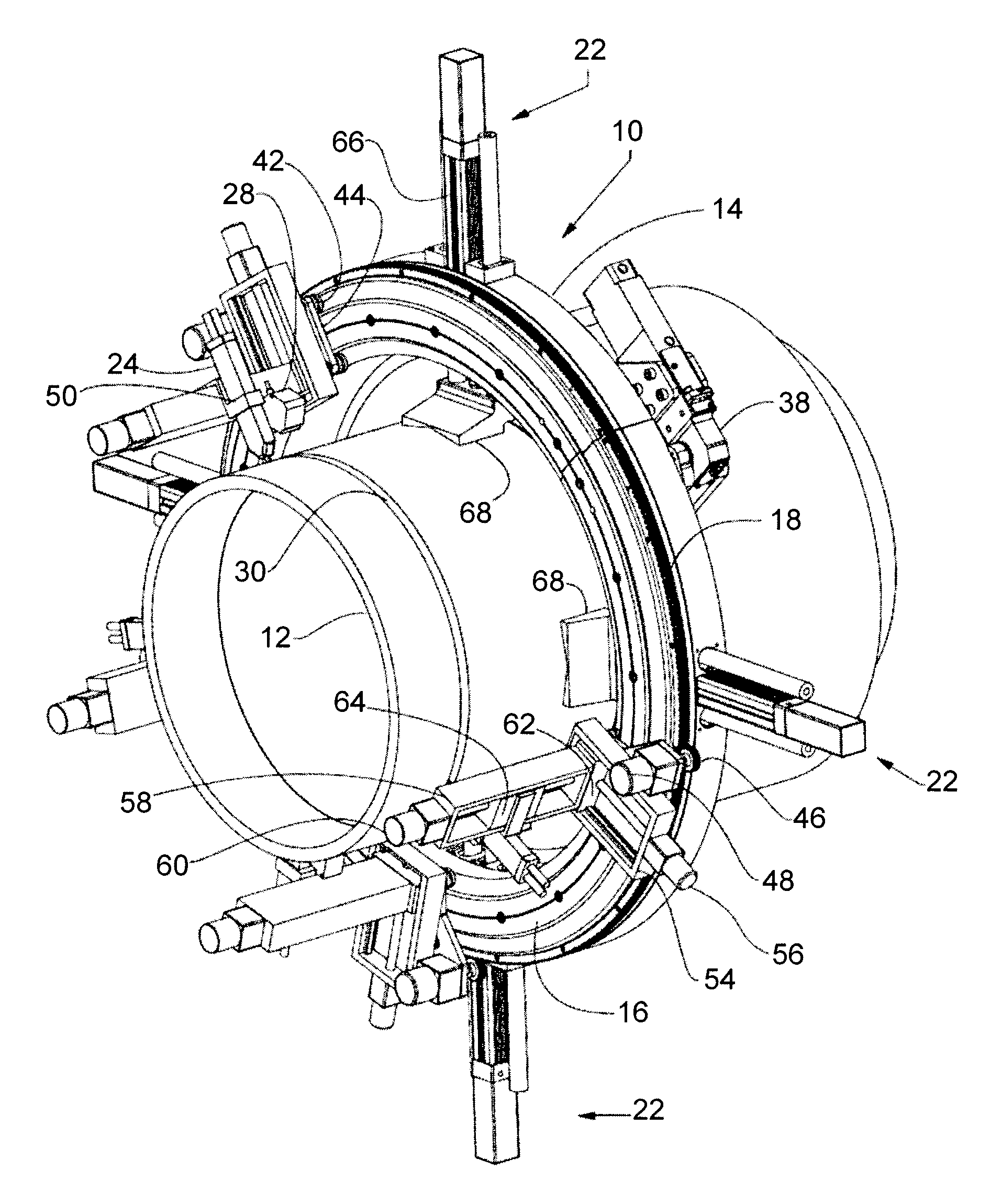
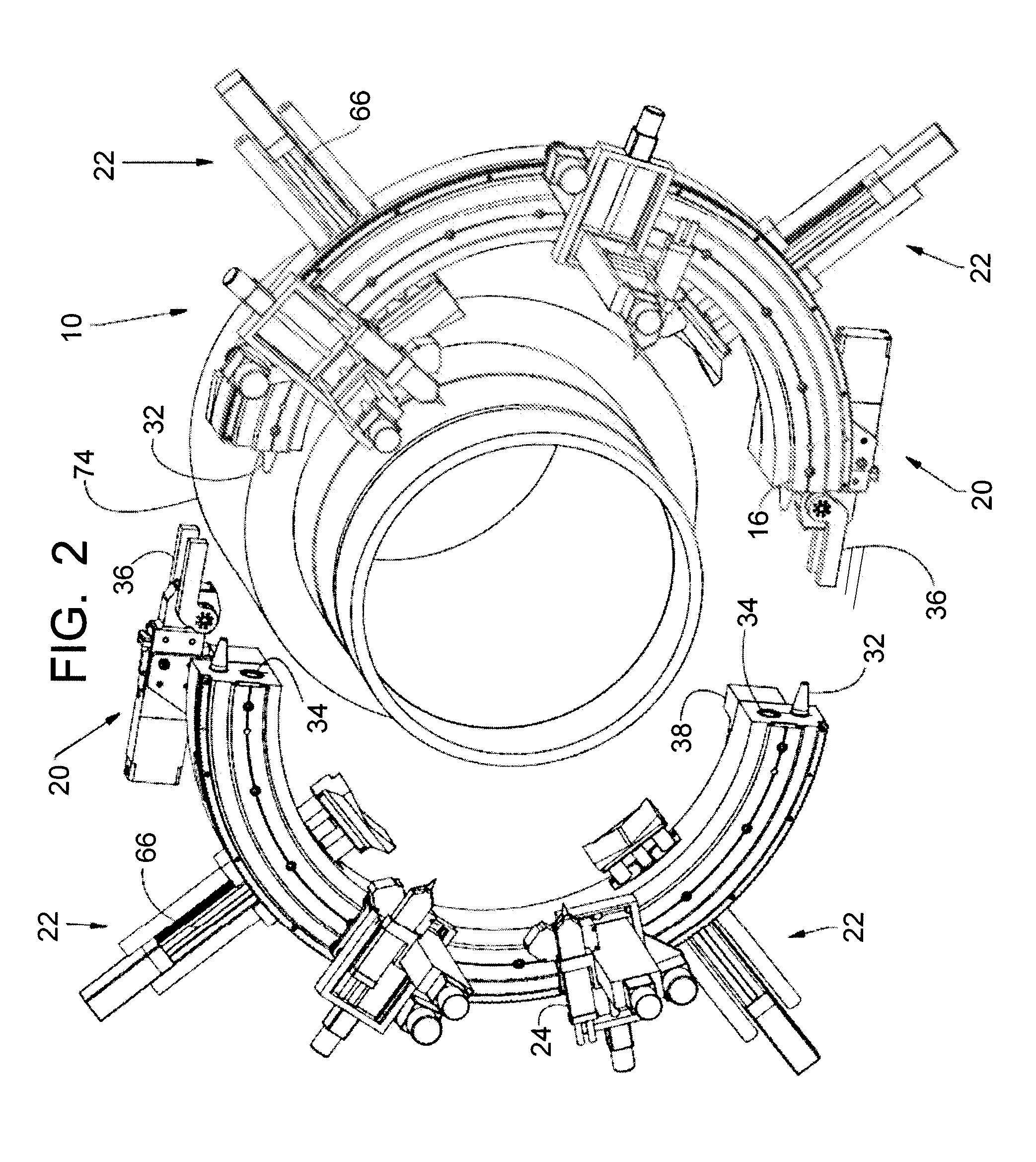
[0011]As seen in FIGS. 2 and 3, the invention is an orbital pipe welding apparatus 10 that is split into two halves designed to be attached together around a pipe segment 12 as seen in FIG. 1. The orbital welding apparatus 10 is generally comprised of two separate backing rings 14, circular race 16, circular gear rack 18, locking means 20 for locking the two backing rings together, means 22 for securing the apparatus 10 in welding position to and around work pieces to be welded together (a pipe segment 12), welding torches 24, means 26 for holding and moving the welding torches 24, and scanning means 28 for scanning and tracking the weld area 30.
[0012]As seen in FIGS. 2 and 3, each backing ring 14 is semi-circular and provided with alignment means such as tapered pins 32 and bores 34 to receive the pins 32. This insures correct alignment of both halves when they are engaged as illustrated in FIG. 1.
[0013]Each half is provided with locking means 20 (attached to the backing rings 14) ...
PUM
| Property | Measurement | Unit |
|---|---|---|
| Area | aaaaa | aaaaa |
| Circumference | aaaaa | aaaaa |
Abstract
Description
Claims
Application Information