Radiation detector, radiographic imaging device and radiographic imaging system

a radiographic imaging and detector technology, applied in the direction of x/gamma/cosmic radiation measurement, radiography controlled devices, instruments, etc., can solve the problems of inability to perform accurate examinations, configuration detection, and limitations in fabrication, so as to achieve easy testing and good precision

Active Publication Date: 2013-01-10
FUJIFILM CORP
View PDF1 Cites 58 Cited by
  • Summary
  • Abstract
  • Description
  • Claims
  • Application Information

AI Technical Summary

Benefits of technology

[0040]According to the above aspects of the present invention, testing...

Problems solved by technology

However, when the radiation detector has pixels with greatly differing configurations (patterns), limitations in fabrication may occur.
Further, when pixels with different configurations are provided, limitations of the specification of inspection devices for the radiation detection elements, issues may occur when testing the radiation detector.
For exampl...

Method used


Image

  • Radiation detector, radiographic imaging device and radiographic imaging system
  • Radiation detector, radiographic imaging device and radiographic imaging system
  • Radiation detector, radiographic imaging device and radiographic imaging system

Examples


first exemplary embodiment

[0064]Explanation follows regarding an example of an exemplary embodiment, with reference to the drawings.

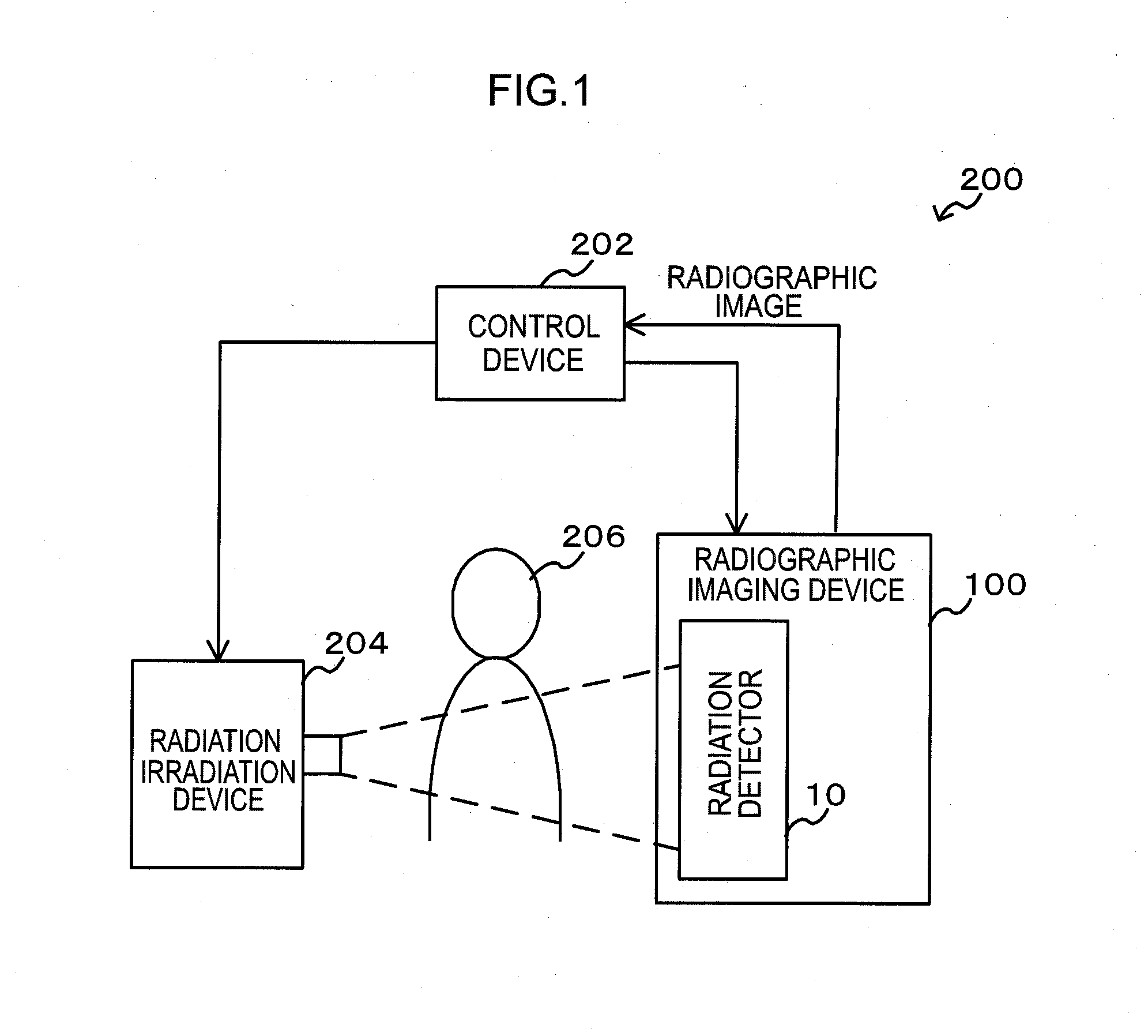
[0065]Explanation first follows regarding a schematic configuration of a radiographic imaging system in which a radiation detector of the present exemplary embodiment is employed. FIG. 1 is a schematic configuration diagram of a radiographic imaging system of the present exemplary embodiment.

[0066]A radiographic imaging system 200 includes a radiation irradiation device 204, a radiographic imaging device 100 equipped with a radiation detector 10, and a control device 202. The radiation irradiation device 204 irradiates radiation (for example X-rays) onto an imaging subject 206. The radiation detector 10 detects radiation irradiated from the radiation irradiation device 204 and that has passed through the imaging subject 206. The control device 202 instructs imaging of a radiographic image and acquires radiographic images from the radiographic imaging device 100. Radiation irradi...

second exemplary embodiment

[0124]Explanation follows regarding a second exemplary embodiment. Since a radiographic imaging system 200 and a radiographic imaging device 100 of the present exemplary embodiment have substantially the same configuration and operation as those of the radiographic imaging system 200 and the radiographic imaging device 100 of the first exemplary embodiment, further explanation of similar portions is omitted. However, the configuration of the pixels 20 (the imaging pixels 20A and the radiation detection pixels 20B) of the present exemplary embodiment differs from the configuration of the pixels 20 (the imaging pixels 20A and the radiation detection pixels 20B) of the first exemplary embodiment, explanation follows regarding the differing configuration.

[0125]FIG. 10 is a plan view illustrating a structure of the imaging pixels 20A according to the present exemplary embodiment. FIG. 11 is a plan view illustrating a structure of the radiation detection pixels 20B according to the presen...

third exemplary embodiment

[0133]Explanation follows regarding a third exemplary embodiment. Since a radiographic imaging system 200 and a radiographic imaging device 100 of the present exemplary embodiment have substantially the same configuration and operation as those of the radiographic imaging system 200 and the radiographic imaging device 100 of the first exemplary embodiment, further explanation of similar portions is omitted. The output destination of charges generated in the sensor portion 103B of the radiation detection pixels 20B of the radiation detector 10 of the present exemplary embodiment, is different to the output destination of charges generated in the sensor portion 103B of the radiation detection pixels 20B of the radiation detector 10 of the first exemplary embodiment, and so explanation follows regarding the differing configuration.

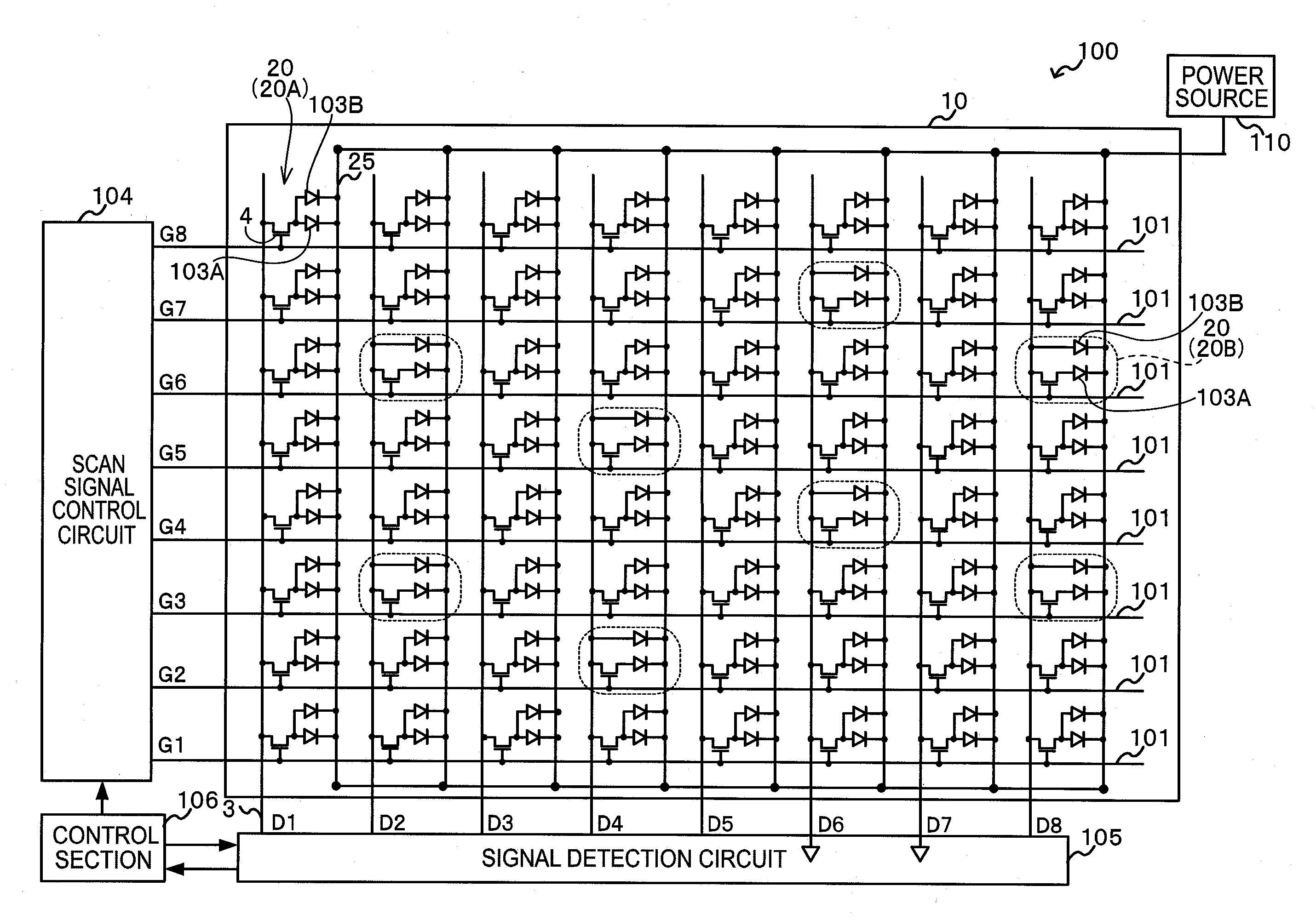
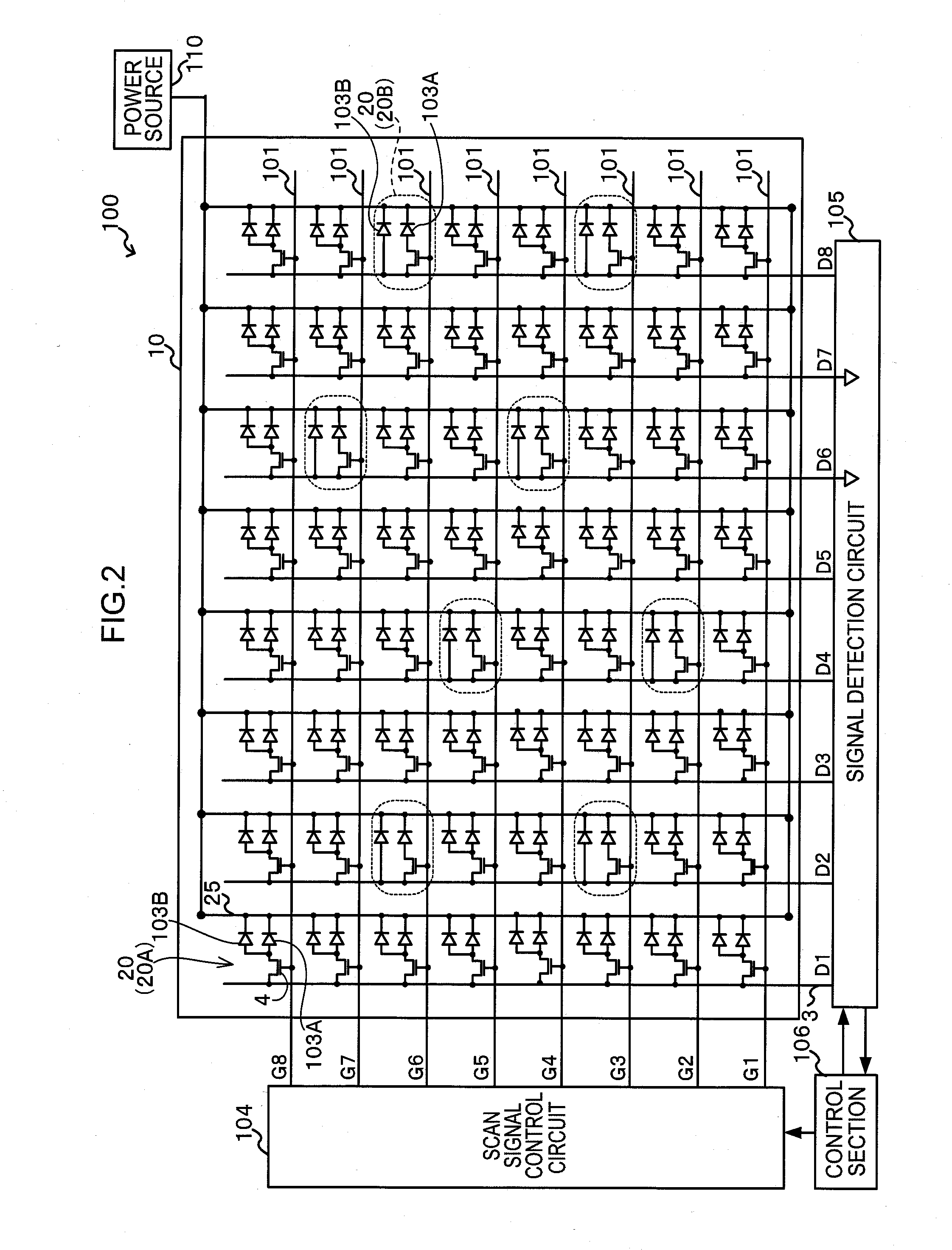
[0134]FIG. 12 illustrates a configuration diagram of an example of an overall configuration of a radiographic imaging device 100 (radiation detector 10) of t...


PUM


Abstract

The present invention provides a radiation detector, a radiographic imaging device, and a radiographic image system that may be easily tested and may precisely detect radiation. Namely, pixels each includes a sensor portion A and a sensor portion B. In imaging pixels, the sensor portion A and the sensor portion B are connected by a connection line, and charges generated in the sensor portion A and in the sensor portion B are read by a TFT switch and output to a signal line. In radiation detection pixels, charges generated in the sensor portion A are read by a TFT switch and output to a signal line. Further, in the radiation detection pixels, the sensor portion B and the signal line are directly connected by a connection line, and the charges generated in the sensor portion B are output to the signal line as they arise.

Description

CROSS-REFERENCE TO RELATED APPLICATION[0001]This application claims priority under 35 USC 119 from Japanese Patent Applications No. 2011-151220, filed on Jul. 7, 2011, and No. 2012-139152, filed on Jun. 20, 2012, the disclosures of which are incorporated by reference herein.BACKGROUND OF THE INVENTION[0002]1. Field of the Invention[0003]The present invention relates to a radiation detector, a radiographic imaging device and a radiographic imaging system. The present invention particularly relates to a radiation detector that accumulates charges generated due to irradiation of radiation, and detects electric signals corresponding to the accumulated charges as data expressing an image, a radiographic imaging device that employs the radiation detector to image radiographic images, and a radiographic imaging system.[0004]2. Description of the Related Art[0005]Radiographic imaging devices for imaging radiographic images are known in which a radiation detector detects radiation that has b...

Claims


Application Information

Patent Timeline
IPC IPC(8): G01T1/24
CPCG01T1/243
Inventor OKADA, YOSHIHIRO
Owner FUJIFILM CORP
Why Eureka
Try Eureka