
Electronic Circuits and Techniques for Maintaining a Consistent Power Delivered to a Load

a technology of electrical circuits and load, applied in the direction of electric variable regulation, process and machine control, instruments, etc., can solve the problems of unfavorable flicker, unnecessarily high power dissipation of switching regulators, and lack of feedback control of dc-dc converters, so as to reduce any fluctuation of power and wide dynamic range

Active Publication Date: 2013-01-10
ALLEGRO MICROSYSTEMS INC
View PDF3 Cites 48 Cited by
  • Summary
  • Abstract
  • Description
  • Claims
  • Application Information

AI Technical Summary

Benefits of technology

The present invention provides circuits and techniques that can provide a wide dynamic range of power to a load while reducing fluctuations in power delivery caused by changes in regulated voltage.

Problems solved by technology

While it is possible to provide a fixed voltage switching regulator that can supply enough voltage for all possible series strings of LEDs, such a switching regulator would generate unnecessarily high power dissipation when driving strings of series connected LEDs having less voltage drop.
If the DC-DC converter is left on when the current through the load is switched off, the DC-DC converter would lack feedback control and the output voltage of the DC-DC converter could move to a different voltage, which is undesirable.
Since, as described above, the common switching regulator is controlled to generate an output voltage only high enough to drive the series connected LED string having the lowest voltage, any voltage dip in the output voltage of the switching regulator can cause a corresponding dip in current supplied to one or more of the series connected LED strings, resulting in an undesirable flicker.
In this case, the regulated output voltage would not recover for some period of time, until the switching regulator recovers, and the flicker would occur.
For reasons described below, DC-DC converters are unable to achieve very short on times when switched on and off.
Thus, for a very short duty cycles, fluctuations in the output voltage of the DC-DC converter can also result in flicker.

Method used


Image

  • Electronic Circuits and Techniques for Maintaining a Consistent Power Delivered to a Load
  • Electronic Circuits and Techniques for Maintaining a Consistent Power Delivered to a Load
  • Electronic Circuits and Techniques for Maintaining a Consistent Power Delivered to a Load

Examples


Embodiment Construction

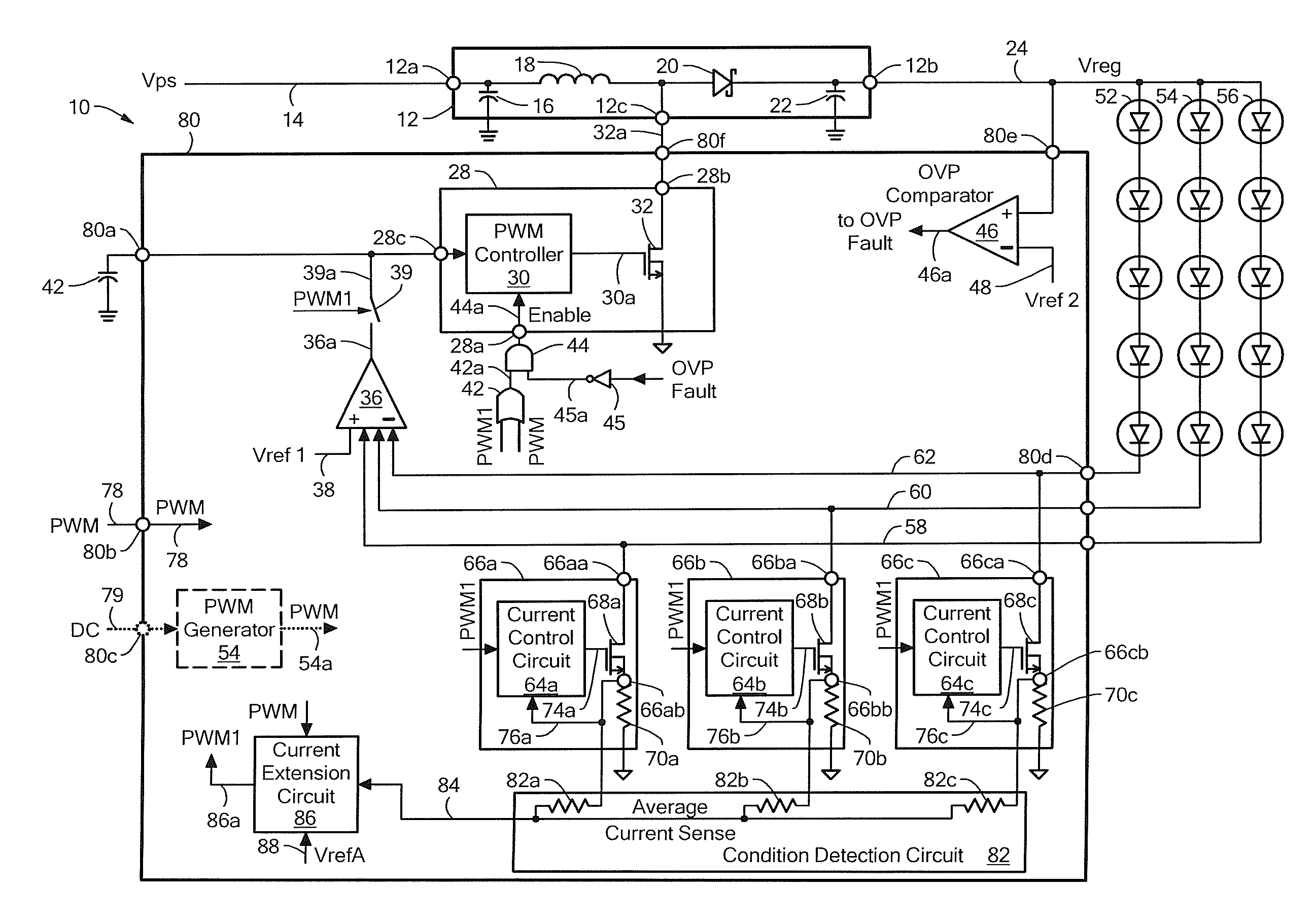
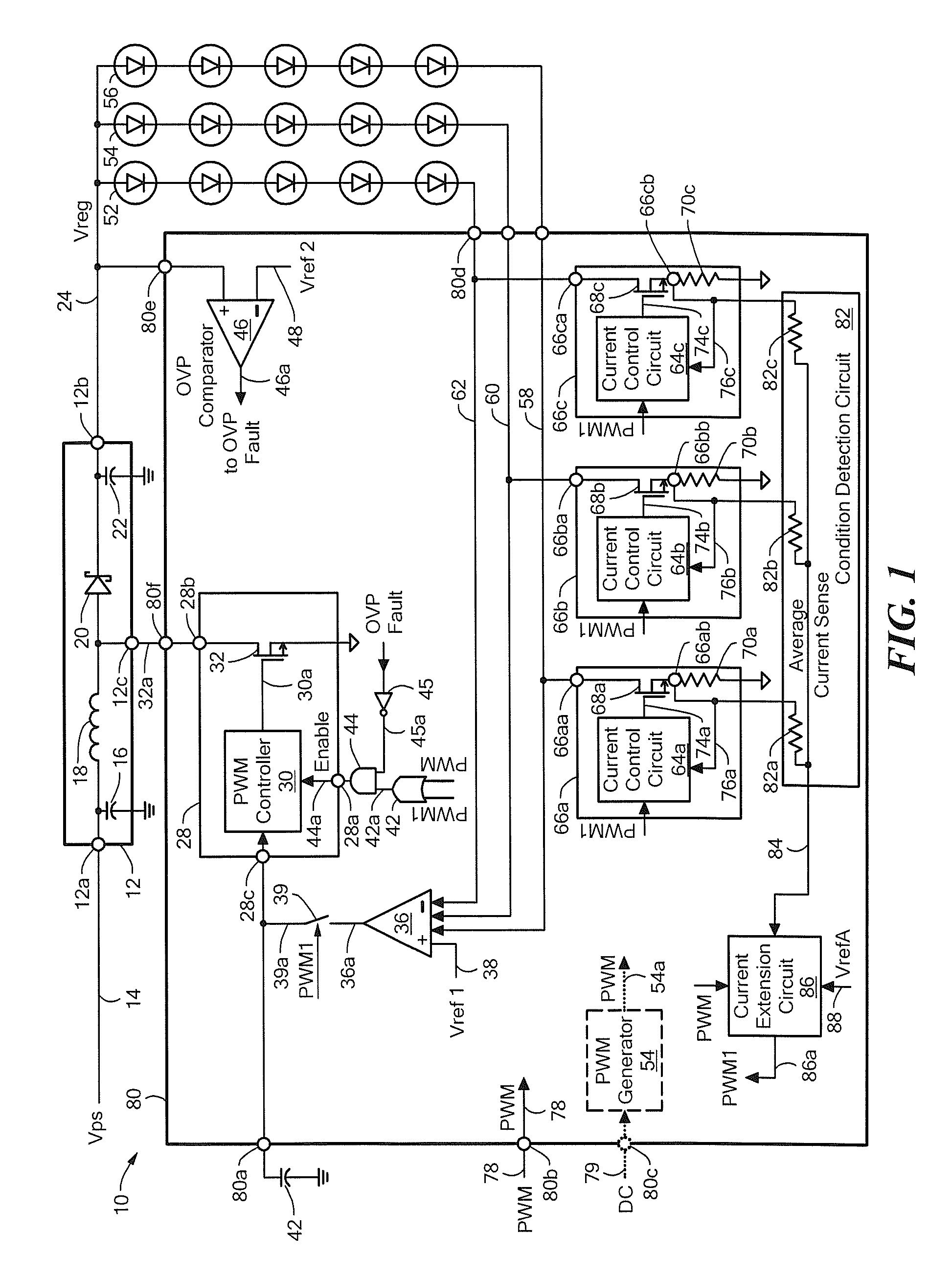
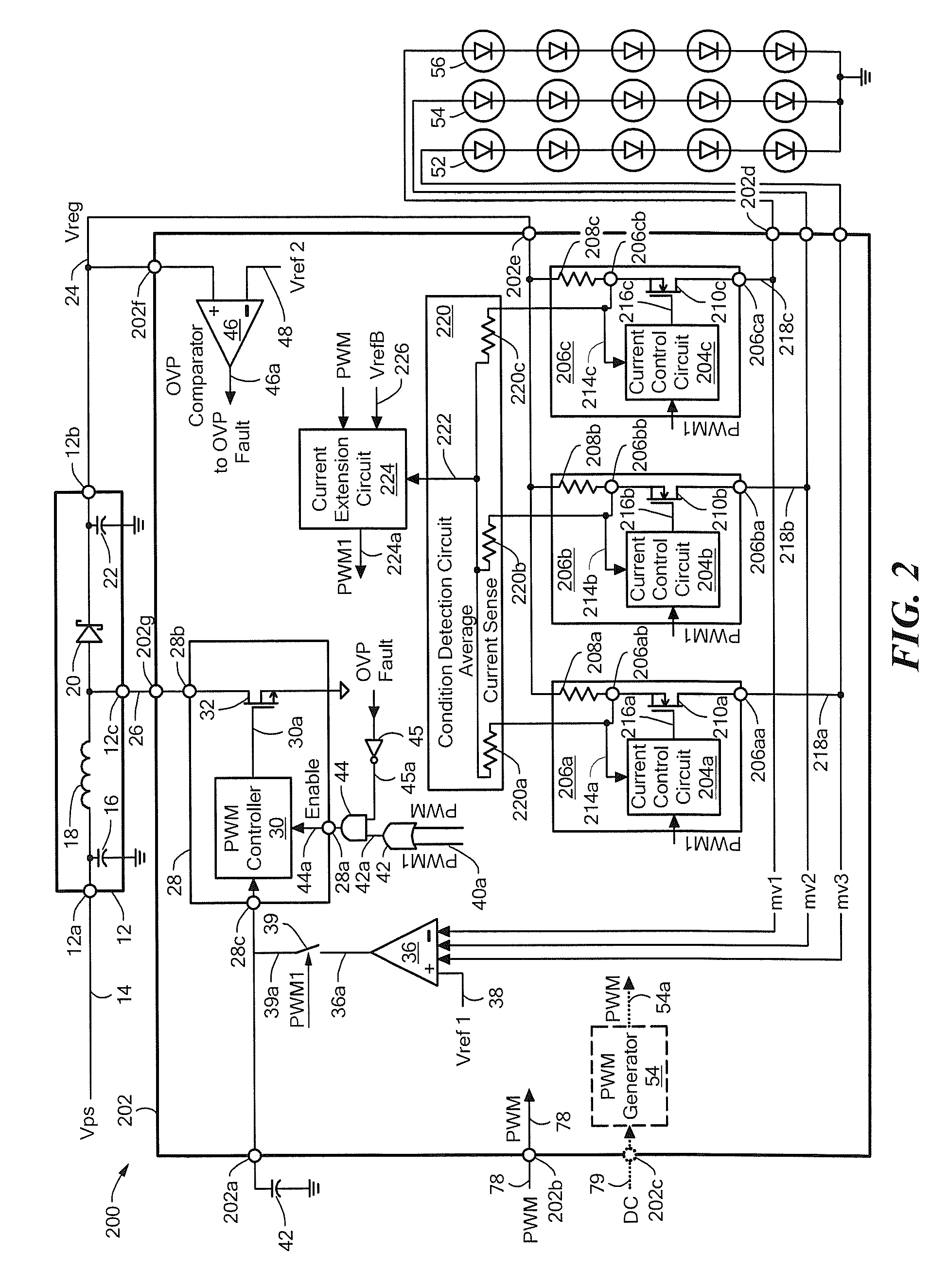
[0036]Before describing the present invention, some introductory concepts and terminology are explained. As used herein, the term “boost switching regulator” is used to describe a known type of switching regulator that provides an output voltage higher than an input voltage to the boost switching regulator. While a certain particular circuit topology of boost switching regulator is shown herein, it should be understood that boost switching regulators have a variety of circuit configurations. As used herein, the term “buck switching regulator” is used to describe a known type of switching regulator that provides an output voltage lower than an input voltage to the buck switching regulator. It should be understood that there are still other forms of switching regulators other than a boost switching regulator and other than a buck switching regulator, and this invention is not limited to any one type.

[0037]DC-DC voltage converters (or simply DC-DC converters) are described herein. The ...


PUM


Abstract

Circuits and methods used therein provide an adjustable average current through a load in accordance with a pulse width modulated (PWM) signal. A condition detection circuit is configured to identify a condition of the electronic circuit and to generate a condition signal indicative of the condition. A current extension circuit is coupled receive the condition signal and coupled to receive the PWM signal. The current extension circuit is configured to generate, at the output node of the current extension circuit, an extended PWM signal having a first state and a second state. The first state of the extended PWM signal longer in time than a first state of the PWM signal by an amount related to a value or a state of the condition signal. Current pulses through the load are extended to be longer in accordance with the extended PWM signal.

Description

CROSS REFERENCE TO RELATED APPLICATIONS[0001]Not Applicable.STATEMENT REGARDING FEDERALLY SPONSORED RESEARCH[0002]Not Applicable.FIELD OF THE INVENTION[0003]This invention relates generally to electronic circuits and, more particularly, to electronic circuits used to drive a load, for example, a light emitting diode (LED) load.BACKGROUND OF THE INVENTION[0004]A variety of electronic circuits are used to drive loads and, more particularly, to control electrical current through strings of series connected light-emitting diodes (LEDs), which, in some embodiments, form an LED display, or, more particularly, a backlight for a display, for example, a liquid crystal display (LCD). It is known that individual LEDs have a variation in forward voltage drop from unit to unit. Therefore, the strings of series connected LEDs can have a variation in forward voltage drop.[0005]Strings of series connected LEDs can be coupled to a common DC-DC converter, e.g., a switching regulator, e.g., a boost sw...

Claims


Application Information

Patent Timeline
IPC IPC(8): H05B37/02G05F1/618H05B44/00
CPCH03K7/08H05B33/0827H05B33/0815H05B45/46H05B45/375H05B45/3725H05B45/39H05B45/38
Inventor SZCZESZYNSKI, GREGORYMANGTANI, VIJAY
Owner ALLEGRO MICROSYSTEMS INC
Features
  • Generate Ideas
  • Intellectual Property
  • Life Sciences
  • Materials
  • Tech Scout
  • Unparalleled Data Quality
  • Higher Quality Content
  • 60% Fewer Hallucinations
Learn More