
Wide bandwidth automatic tuning circuit

Active Publication Date: 2013-01-10
HRL LAB
View PDF1 Cites 22 Cited by
  • Summary
  • Abstract
  • Description
  • Claims
  • Application Information

AI Technical Summary

Benefits of technology

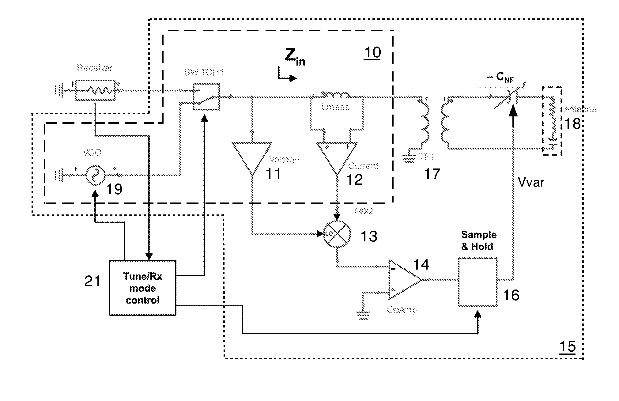
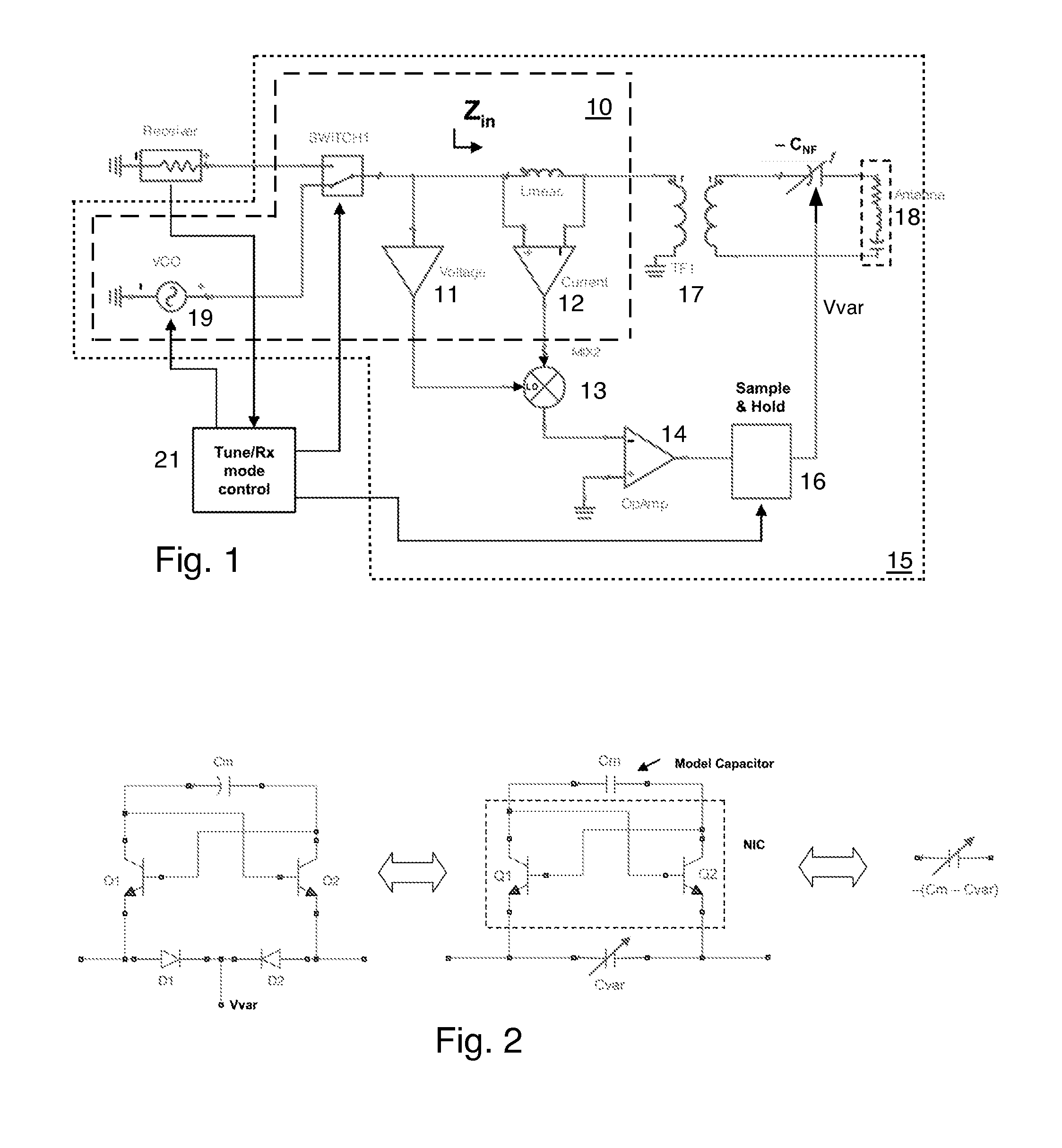
The present invention provides an automatic tuning circuit for matching an antenna to a radio receiver or a variable frequency oscillator. The circuit includes a tunable non-Foster circuit and sensing and feedback circuits. The sensing circuit senses the combined reactance of the tunable non-Foster circuit and the antenna, and the feedback circuits tune the tunable non-Foster circuit to automatically minimize the combined reactance. This allows for easy and automatic adjustment of the tuning circuit, improving the efficiency of the signal transfer between the radio receiver or variable frequency oscillator and the antenna.

Problems solved by technology

The useable radio spectrum is limited and traditionally the available spectrum has been licensed to particular users or groups of users by governmental agencies, such as the Federal Communications Commission in the United States.
In the article “The End of Spectrum Scarcity” published by IEEE Spectrum, the authors note that while some available spectrum is congested, much of it is underutilized.
It is well known that the performance of electrically-small antennas (ESAs) is limited when using traditional (i.e. passive) matching networks.
Specifically, ESAs have high quality factor, leading to a tradeoff between bandwidth and efficiency.
But due to their smallness, they can be very narrow banded.
This has two disadvantages: 1) the bandwidth is narrow due to the use of a passive tuning circuit, which necessitates the use of coarse (frequency sensing) and fine adjust, and 2) the motor driven tuning is slower than electronic tuning.
There are two related problems with this approach that need to be addresses before non-Foster matching is robust enough to be deployed in products: stability and accuracy.
Negative capacitance is achieved using feedback circuits whose stability depends on both the internal circuit parameters and the load impedance; instability leads to either oscillation (i.e. emission of a periodic waveform from the circuit) or latchup.
Unfortunately, the optimal impedance match typically occurs near the point where the stability margin goes to zero.
(3)), then the match is unstable.
But accuracy and stability are related since the accuracy (or lack thereof) by which components can be manufactured will impact the likelihood of an unstable situation arising by reason of the combined antenna impedance and match network impedance being negative.
Component and manufacturing tolerances, as well as temperature and environmental loading effects, suggest that even a 10% error may be challenging to achieve using prior art non-Foster circuits.

Method used


Image

  • Wide bandwidth automatic tuning circuit
  • Wide bandwidth automatic tuning circuit
  • Wide bandwidth automatic tuning circuit

Examples


Embodiment Construction

[0025]This invention provides an automatically-tuning non-Foster matching circuit, which automatically drives the input reactance (Xin) to zero at one frequency where Xin is the imaginary part of the input impedance (Zin), so Zin=Rin+jXin. It is well known that the performance of electrically-small antennas (ESAs) is limited when using traditional (i.e. passive) matching networks due to their high antenna Q. Non-Foster Circuits (NFCs) can reduce the antenna reactance by orders of magnitude by synthesizing negative capacitance or negative inductance, which are then placed in series (for example, when using negative capacitance to match monopole or dipole antennas) or parallel (for example, when using negative inductance to match slot or loop antennas) such that they cancel the antenna reactance over a broad bandwidth. A high degree of accuracy is desired to effectively cancel large antenna reactances. In addition, NFCs are conditionally stable, and typically have a very small stabili...


PUM


Abstract

An automatic tuning circuit for matching an antenna to a radio receiver. The automatic tuning circuit includes a tunable non-Foster circuit for coupling the receiver and the antenna; and sensing and feedback circuits for sensing the combined capacitance of the tunable non-Foster circuit and the antenna and for tuning the tunable non-Foster circuit to automatically minimize the combined capacitance of the tunable non-Foster circuit and the antenna.

Description

CROSS REFERENCE TO RELATED APPLICATIONS[0001]This application is a continuation in part of U.S. patent application Ser. No. 13 / 177,479 filed on Jul. 6, 2011 and entitled “Wide Bandwidth Automatic Tuning Circuit”, the disclosure of which is hereby incorporated herein by reference.[0002]This application is also related to and claims the benefit of U.S. Provisional Patent Application Ser. No. 61 / 505,037 filed on Jul. 6, 2011 and entitled “Differential negative impedance converters and inverters with tunable conversion ratios”, the disclosure of which is hereby incorporated herein by reference.TECHNICAL FIELD[0003]This invention relates to a wide bandwidth automatic tuning circuit. Automatic tuning circuits are used to connect a transmitter and / or a receiver to an antenna with a better impedance match than if the transmitter and / or the receiver were directly connected to the antenna.BACKGROUND[0004]The useable radio spectrum is limited and traditionally the available spectrum has been l...

Claims


Application Information

Patent Timeline
IPC IPC(8): H03H7/40H01Q1/50
CPCH03H7/40H03H11/30
Inventor WHITE, CARSON R.COLBURN, JOSEPH S.YUNG, MICHAEL W.HITKO, DONALD A.
Owner HRL LAB
Learn More