
Generating a depth map from a two-dimensional source image for stereoscopic and multiview imaging

a two-dimensional source image and depth map technology, applied in the field of depth maps generated from monoscopic source images, can solve the problems of insufficient depth maps, difficulty in generating depth maps with adequate accuracy, and insufficient computational cost, and achieve the effect of saving bandwidth requirements

Inactive Publication Date: 2013-01-10
HER MAJESTY THE QUEEN & RIGHT OF CANADA REPRESENTED BY THE MIN OF IND THROUGH THE COMM RES CENT
View PDF2 Cites 27 Cited by
  • Summary
  • Abstract
  • Description
  • Claims
  • Application Information

AI Technical Summary

Benefits of technology

[0043]expanding spatial location of each depth value by a predetermined number of pixels to increase width of the identified subset of the array of pixels representing the edge.
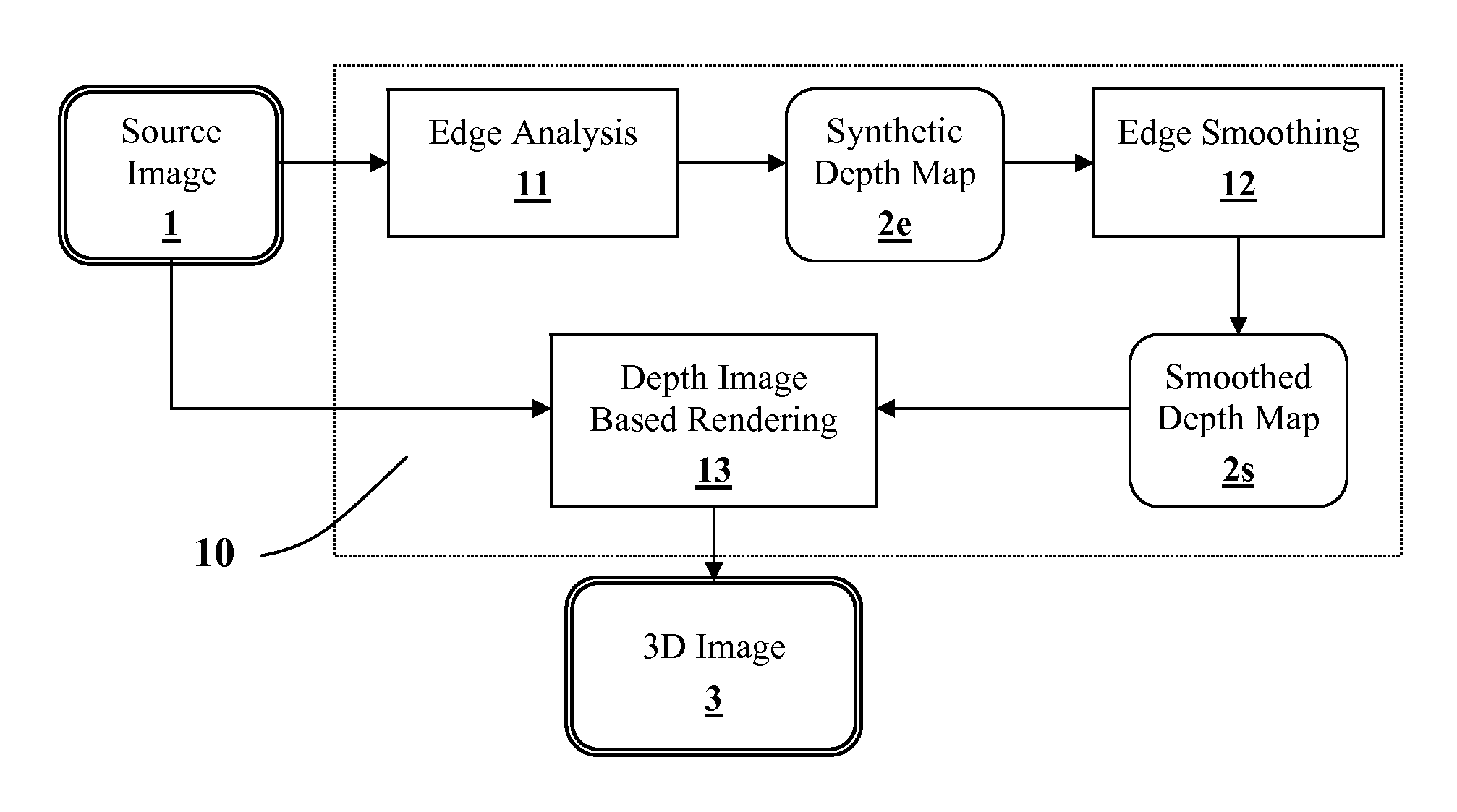
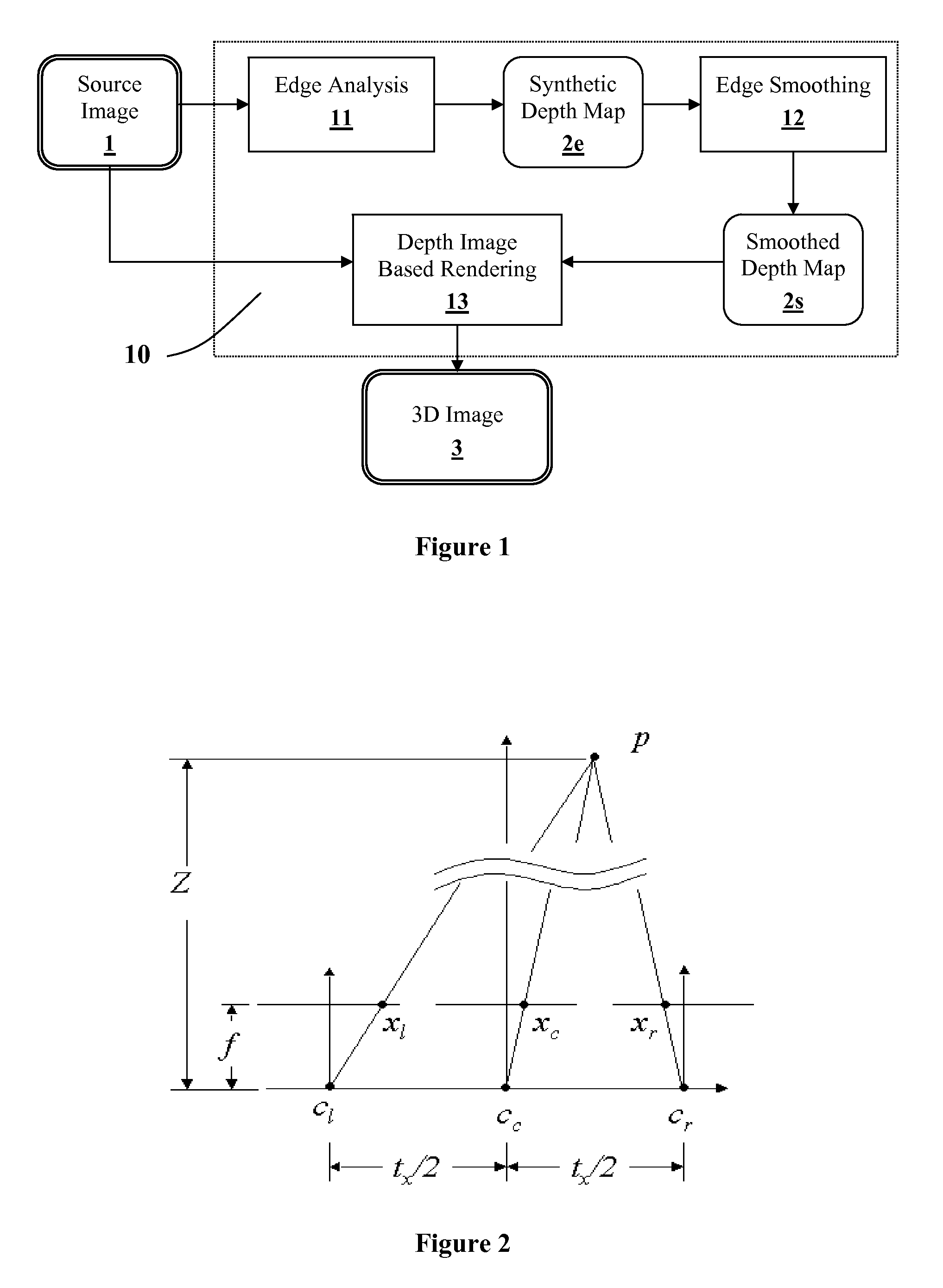
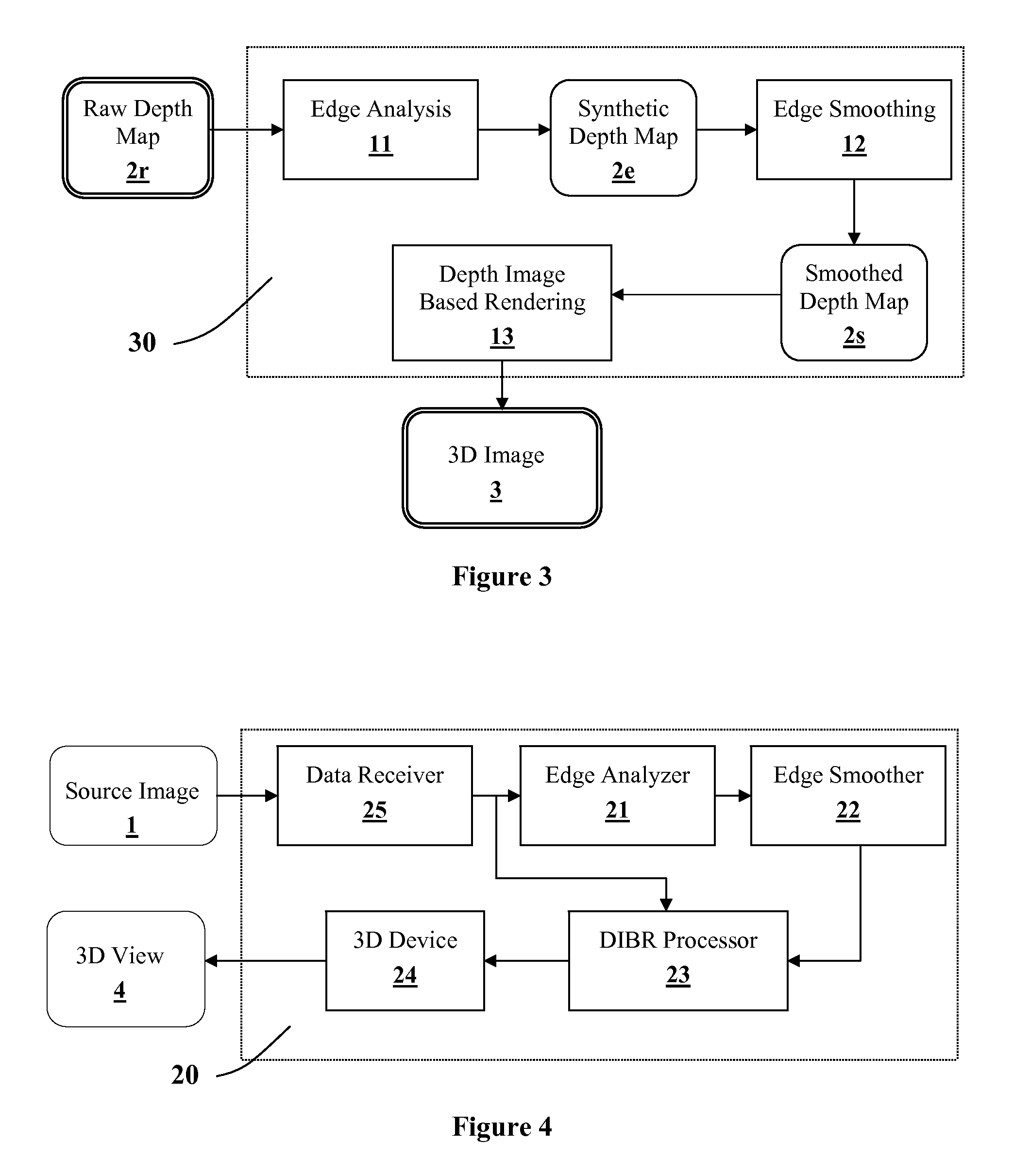
[0054](b) smoothing the depth map to a near-saturation level around an area corresponding to at least one local region of the source image defined by a change in depth exceeding a predefined threshold, so as to minimize dis-occluded regions around each edge, wherein range and strength of smoothing are substantially higher in the vertical than the horizontal orientation.
[0064]A major advantage of the system and methods provided by this invention is that they address both issues of depth map generation and depth-image-based rendering (DIBR) without annoying artifacts at object boundaries. In this respect, the invention provides methods for generating a novel type of depth maps containing sparse information concentrated at edges and boundaries of objects within the source image, to serve the purpose of savings in bandwidth requirements for either storage or transmission. This is in contrast with conventional depth maps containing dense information about the absolute or relative depth of objects of a given image with no particular emphasis on edges and boundaries of objects.

Problems solved by technology

The fundamental problem of working with multiview and stereoscopic images is that multiple images are required, as opposed to a single stream of monoscopic images for standard displays.
A major problem with conventional DIBR is the difficulty in generating the depth maps with adequate accuracy, without a need for much manual input and adjustments, or without much computational cost.
Another problem arises with such dense depth maps for motion picture applications, where the depth map is too dense to allow adequately fast frame-to-frame processing.
However, the resulting depth maps are likely to contain undesirable blocky artifacts, depth instabilities, and inaccuracies, because the problem of finding matching features in a pair of stereoscopic images is a difficult problem to solve.
However, the main problem with these attempts is that depth within object boundaries is still difficult to determine and, for the described methods, attempts are made to fill the regions which tend to be inaccurate, as well as computationally complex and intensive.
Another major problem with DIBR concerns the rendering of newly exposed regions that occur at the edges of objects where the background was previously hidden from view, and no information is available in depth maps on how to properly fill in these exposed regions or “holes” in the rendered images.
However, this solution often leads to visible distortions or annoying artifacts at edges of objects.
More recently, however, we found that uniform smoothing of depth maps causes undesirable geometrical distortion in the newly exposed regions as further described below.
Another limitation of conventional methods in DIBR, in general, is likely to occur when applied to motion pictures entailing a sequence of image frames.
Any sharp frame-to-frame transitions in depth within a conventional depth map, often result in misalignment of a given edge depth between frames thereby producing jerkiness when the frames are viewed as a video sequence.

Method used


Image

  • Generating a depth map from a two-dimensional source image for stereoscopic and multiview imaging
  • Generating a depth map from a two-dimensional source image for stereoscopic and multiview imaging
  • Generating a depth map from a two-dimensional source image for stereoscopic and multiview imaging

Examples


Embodiment Construction

[0070]Reference herein to any embodiment means that a particular feature, structure, or characteristic described in connection with the embodiment can be included in at least one embodiment of the invention. The appearances of the phrase “in one embodiment” in various places in the specification are not necessarily all referring to the same embodiment, nor are separate or alternative embodiments mutually exclusive of other embodiments.

[0071]In context of the present invention, the following general definitions apply. A source image is a picture, typically digital and two-dimensional planar, containing an image of a scene complete with visual characteristics and information that are observed with one eye, such as luminance intensity, shape, colour, texture, etc.

[0072]A depth map is a two-dimensional array of pixels (or blocks of pixels) each being assigned a depth value indicating the relative or absolute depth of the part of objects in the scene, depicted by the pixel (or block) fro...


PUM


Abstract

Depth maps are generated from a monoscopic source images and asymmetrically smoothed to a near-saturation level. Each depth map contains depth values focused on edges of local regions in the source image. Each edge is defined by a predetermined image parameter having an estimated value exceeding a predefined threshold. The depth values are based on the corresponding estimated values of the image parameter. The depth map is used to process the source image by a depth image based rendering algorithm to create at least one deviated image, which forms with the source image a set of monoscopic images. At least one stereoscopic image pair is selected from such a set for use in generating different viewpoints for multiview and stereoscopic purposes, including still and moving images.

Description

CROSS-REFERENCE TO RELATED APPLICATIONS[0001]This application claims priority from U.S. Provisional Patent Application No. 60 / 702,276 filed on Jul. 26, 2005, which is incorporated herein by reference for all purposes.TECHNICAL FIELD[0002]The present invention generally relates to depth maps generated from a monoscopic source image, for use in creating deviated images with new camera viewpoints for stereoscopic and multiview displays, and in particular to asymmetrically smoothed sparse depth maps.BACKGROUND TO THE INVENTION[0003]The viewing experience of visual displays and communication systems can be enhanced by incorporating multiview and stereoscopic (3D) information that heighten the perceived depth and the virtual presence of objects depicted in the visual scene. Given this desirable feature and with the maturation of digital video technologies, there has been a strong impetus to find efficient and commercially viable methods of creating, recording, transmitting, and displaying...

Claims


Application Information

Patent Timeline
Patent Type & Authority Applications(United States)
IPC IPC(8): G06T15/00
CPCG06T7/0067G06T7/0085G06T2207/10012G06T2207/10016H04N13/0282G06T2207/20228H04N13/026H04N13/0275G06T2207/10028G06T7/564G06T7/13H04N13/275H04N13/282H04N13/261
Inventor TAM, WA JAMESZHANG, LIANG
Owner HER MAJESTY THE QUEEN & RIGHT OF CANADA REPRESENTED BY THE MIN OF IND THROUGH THE COMM RES CENT
Learn More